Latch locking apparatus for a frameless glass door

Inactive Publication Date: 2008-03-27
DOOR & WINDOW HARDWARE
View PDF16 Cites 4 Cited by
  • Summary
  • Abstract
  • Description
  • Claims
  • Application Information

AI Technical Summary

Benefits of technology

[0008]The main objective of the present invention is to provide a latch locking appa

Problems solved by technology

1. Users cannot hold the glass door in a close position unless the conventional glass locking apparatus is locked.
2. In general, a user can rotate the key

Method used


Image

  • Latch locking apparatus for a frameless glass door
  • Latch locking apparatus for a frameless glass door
  • Latch locking apparatus for a frameless glass door

Examples


Example

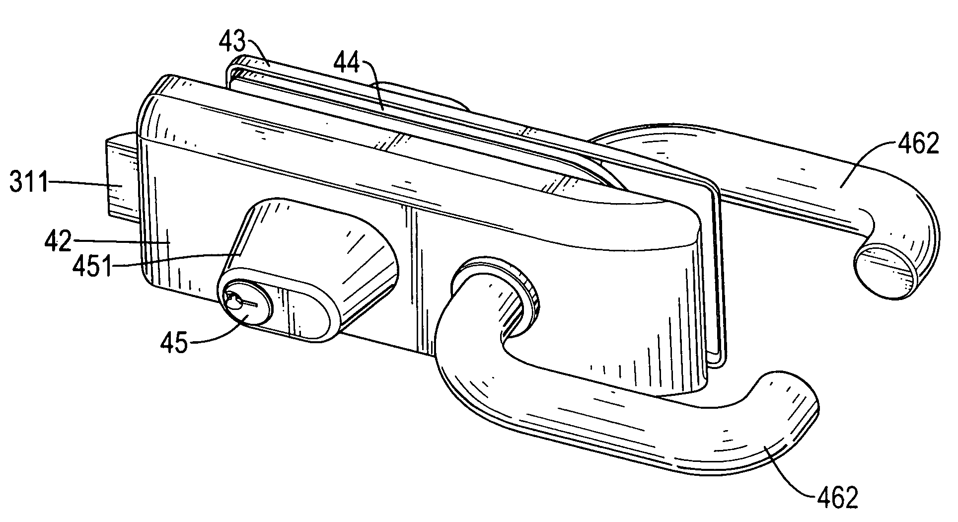
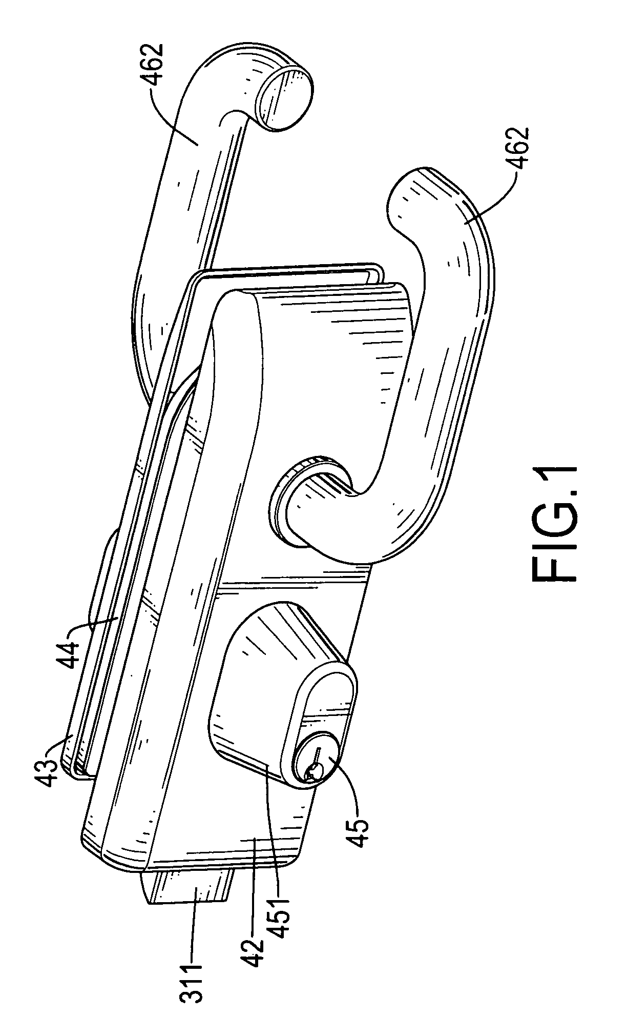
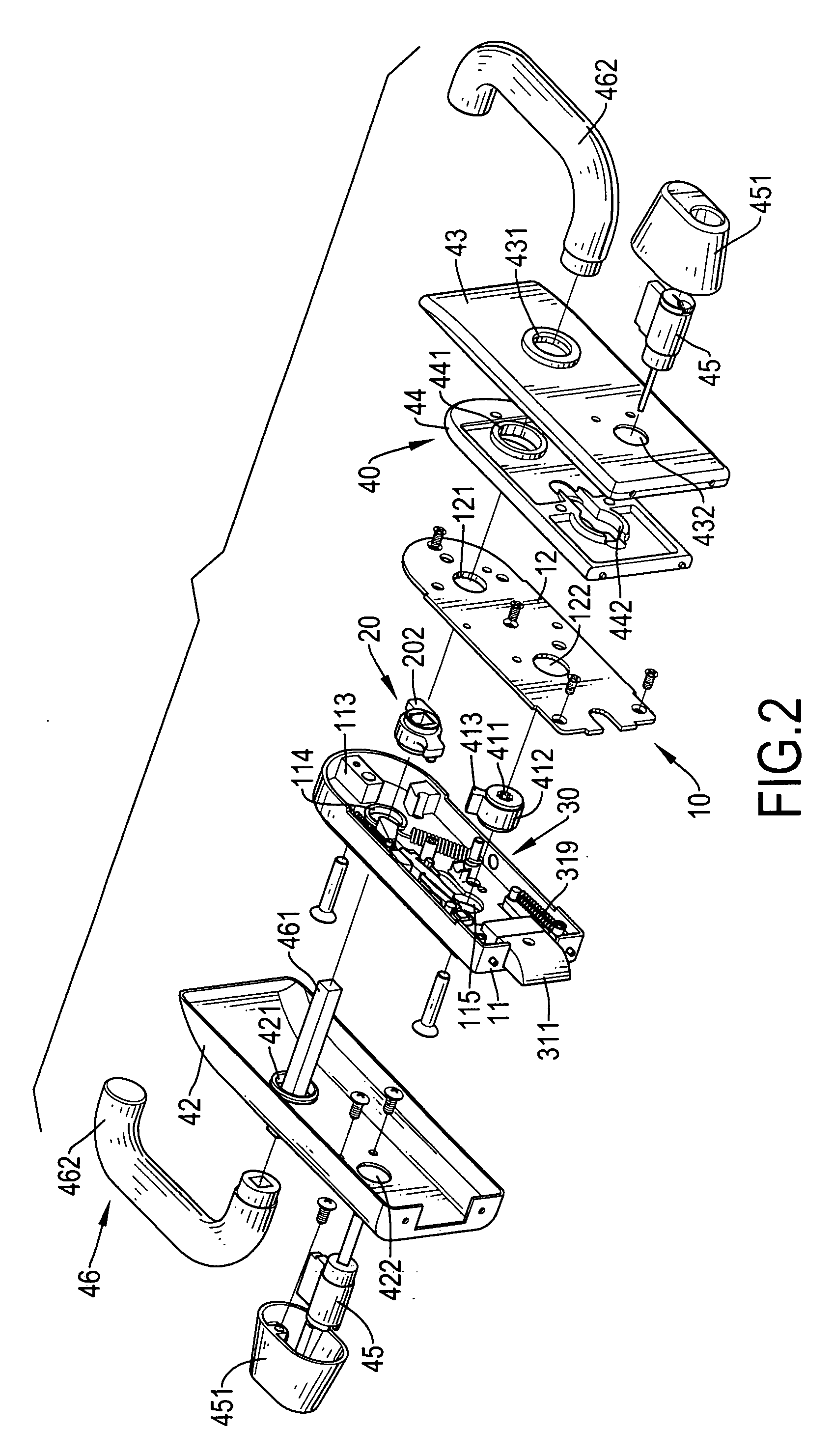
[0022]With reference to FIGS. 1 to 4, a latch locking apparatus in accordance with the present invention is used on a glass door and comprises a body (10), an operating member (20), a transmitting device (30) and a lock device (40).

[0023]The body (10) is attached to the glass door and has a casing (11) and a cover (12). The casing (11) is attached to the glass door and has an open top, a closed bottom, an upper sidewall, a lower sidewall, a distal end, a proximal end, a chamber (112), an opening (111), an upper restricting block (113), a lower restricting block (113′), a mounting hole (114), a connecting hole (115), an upper mounting post (116), a lower mounting post (117) and a recess (119).

[0024]The chamber (112) is defined in the casing (11) between the open top and the closed bottom.

[0025]The opening (111) is formed through the distal end of the casing (11) and communicates with the chamber (112).

[0026]The upper restricting block (113) is formed on the closed bottom of the casin...


PUM


Abstract

A latch locking apparatus for a glass door has a body, an operating member, a transmitting device and a lock device. The body has a casing with a mounting hole and a lower mounting post. The operating member is mounted in the casing and has a pulling arm, a mounting post and a first spring. The mounting post is formed on the pulling arm. The transmitting device is mounted in the casing and has a latch plate, a transmitting lever and a pulling bar. The latch plate is mounted in the casing and has a second spring. The transmitting lever is connected to the latch plate. The pulling bar is connected to the transmitting lever and has a third spring. The lock device is connected to the body and the operating member.

Description

BACKGROUND OF THE INVENTION[0001]1. Field of the Invention[0002]The present invention relates to a latch locking apparatus, and more particularly relates to a latch locking apparatus with handle and key for frameless glass door locking and opening.[0003]2. Description of Related Art[0004]With reference to FIG. 11, a conventional glass locking apparatus (60) is mounted on a bottom or a middle of a glass door to lock the glass door to prevent unauthorized access to a room. The conventional glass locking apparatus usually has a body (61), a lock device (63) and a bolt (64). The body (61) has two mounting slabs and two connecting blocks (62). The mounting slabs are connected against the glass door. Each connecting block (62) is formed on the mounting slab opposite the glass door and has a mounting hole. The mounting hole is formed through the connecting block (62) and a corresponding mounting slab. The lock device (63) is defined in the mounting hole and connected to the body (61), is a...

Claims


Application Information

Patent Timeline
IPC IPC(8): E05B13/10
CPCE05B65/0025E05B55/06Y10T70/577Y10T292/0969Y10T292/1015Y10T292/0974Y10T70/5173
Inventor CHANG, WEI-HUNGLIN, CHING-KO
Owner DOOR & WINDOW HARDWARE
Why Eureka
Try Eureka