Trigger actuated cable clamp

a technology of trigger and cable clamp, which is applied in the direction of couplings, rod connections, manufacturing tools, etc., can solve the problems of installationer with too short cable length, tendency for splicing to fail, and relatively susceptible to premature triggering or firing, so as to prevent the premature release of stored energy

Active Publication Date: 2007-05-22
HUBBELL INC
View PDF18 Cites 28 Cited by
  • Summary
  • Abstract
  • Description
  • Claims
  • Application Information

AI Technical Summary

Benefits of technology

[0007]An object of the present invention is to provide a cable clamp which prevents the premature release of stored energy prior to insertion of the cable.
[0008]Another object of the present invention is to provide a cable clamp which enables an installer to relatively easily ascertain full insertion of the cable so that mechanical failure due to improper installation is prevented.
[0009]A further object of the present invention is to provide a cable clamp that is relatively simple to assemble, use, manufacture, and package.

Problems solved by technology

This situation leaves the installer with too short a length of cable.
In this event, the line may be energized, but, there is still a propensity for the splice to fail under wind, vibration, ice, or other additional loading that may occur during future use.
One drawback of this device is that it is relatively susceptible to premature triggering or firing.
In a splicing operation, premature triggering could occur on one end of the device, leaving the other end operational.
Since this condition would not be readily apparent to the installer, the unit might accidentally be installed on the non-triggered end, if one exists, only to find the other end triggered.

Method used


Image

  • Trigger actuated cable clamp
  • Trigger actuated cable clamp
  • Trigger actuated cable clamp

Examples


Embodiment Construction

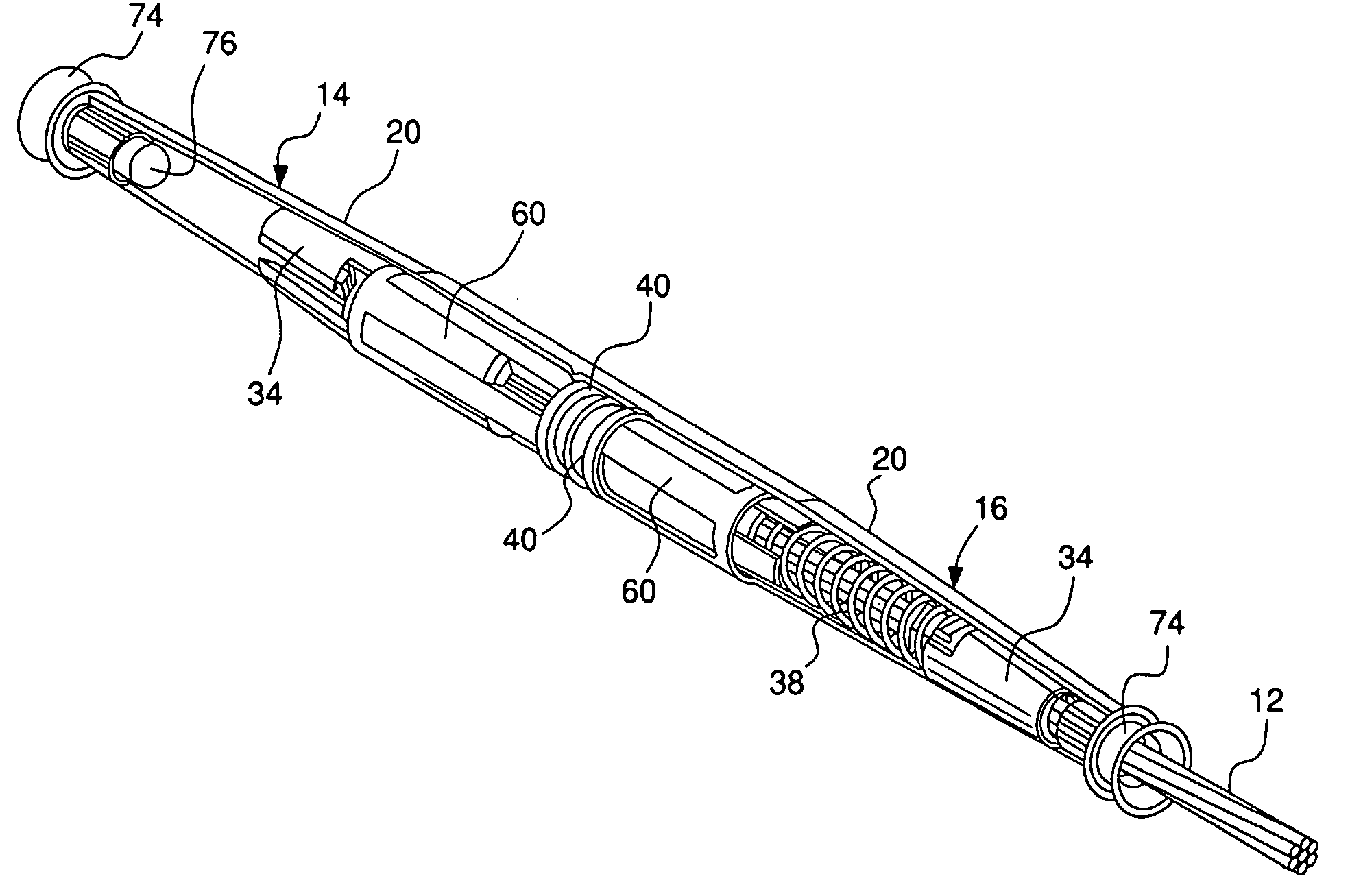
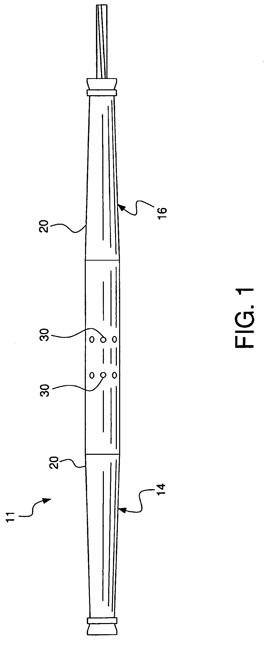
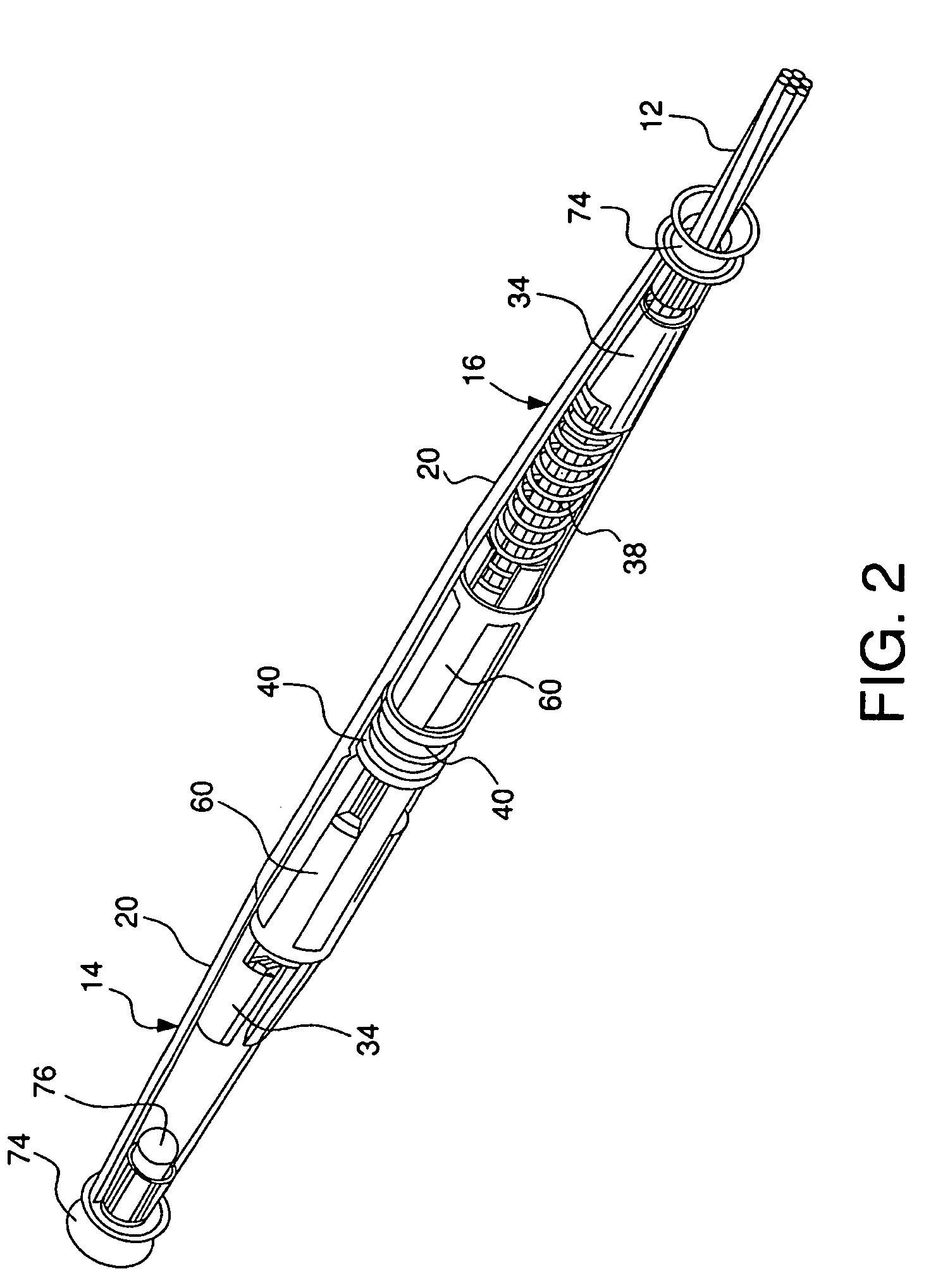
[0025]FIGS. 1–10 illustrate a splicing connector 11 for a cable 12 having first and second cable clamps 14 and 16, each cable clamp 14 and 16 being a mirror image of the other. In the exemplary embodiment, the cable clamps 14 and 16 are used to make an electrical and a mechanical connection (e.g. splicing); however, a single clamp assembly may be used to establish a mechanical connection. As best seen in FIG. 2, each clamp 14 and 16 includes a housing 20, a jaw assembly 34, a biasing member 38, a trigger 60, a retainer 40, a guide cup 76, and a funnel guide 74. In FIG. 2, the jaw assembly 34 of cable clamp 14 is in the locked position and the jaw assembly of cable clamp 16 is in the triggered position.

[0026]In FIGS. 3–5, each housing 20 is substantially conically shaped, tapers in an opposite direction, and has a receiving opening 22. Each housing 20 may be fabricated of a suitable material such as steel or aluminum. An interior cavity 24 (FIG. 3) extends between first and second en...


PUM


Abstract

A clamp for a cable having a housing with a first end, a second end, and an interior cavity to receive the cable. The clamp also includes a jaw assembly having a notch. The jaw assembly moves between locked and triggered positions within the cavity. A biasing member is disposed within the cavity to bias the jaw assembly towards the triggered position. A retainer is arranged within the cavity and has gripping fingers to engage the notches in the locked position. A trigger is positioned within the cavity. The trigger has an outer locking portion to engage with the gripping fingers to releasably secure the gripping fingers in the notches to retain the jaw assembly in the locked position. When the cable is inserted into the interior cavity and contacts the trigger device, the gripping fingers and notches disengage so that the biasing member biases the jaw assembly towards the first end of the clamp to clamp the cable.

Description

FIELD OF THE INVENTION[0001]The present invention relates to a cable clamp. More particularly, the present invention relates to a trigger actuated cable clamp which is activated by contact from the end of a cable to initiate the release of a jaw assembly.BACKGROUND OF THE INVENTION[0002]One type of cable connector is the automatic splice. The automatic splice is commonly used by utility linemen to quickly splice ends of suspended cable together. Automatic splices generally include a tapered clamp body or shell to house a pair of jaw assemblies and a spring. The jaws are shaped to cooperate with the clamp body so that a cable gripping surface applies an ever increasing clamping force on the cable as it travels through the clamp body towards a cable receiving opening.[0003]U.S. Pat. No. 5,334,056 to Hlinsky, discloses a relatively complex automatic cable connector configured for electrical and mechanical or only mechanical connections. The device includes a hammer 16 that is moved to ...

Claims


Application Information

Patent Timeline
Patent Type & Authority Patents(United States)
IPC IPC(8): F16G11/00F16G11/04
CPCF16G11/04F16G11/10H01R4/52Y10T24/3969Y10T24/3973Y10T403/7064Y10T24/3956Y10T403/5793Y10T24/3996F16G11/106
Inventor TAMM, CARL R.HAY, ROBERT G.SIEGRIST, STANLEY R.
Owner HUBBELL INC
Why Eureka
Try Eureka