Downhole magnetic retrieval tool

a magnetic retrieval and tool technology, applied in the direction of fluid removal, borehole/well accessories, cleaning processes and apparatuses, etc., can solve the problems of physical damage to exposed magnets, different types of metal debris in wells, and tools practicably limited to retrieving cutting, etc., to achieve convenient cleaning and repair

Active Publication Date: 2007-05-22
BILCO TOOLS
View PDF23 Cites 47 Cited by
  • Summary
  • Abstract
  • Description
  • Claims
  • Application Information

AI Technical Summary

Benefits of technology

[0011]A significant feature of the invention is that the magnets are reliably held within the tool body, yet may be easily removed from the tool body in a field operation for repair or cleaning.
[0013]A significant advantage of the tool and method is that the tool may be used and easily cleaned and repaired in a field operation.

Problems solved by technology

When drilling an oil or gas well, or when refurbishing an existing well, normal operations may result in various types of metal debris in a well.
Some tools practically may be limited to retrieving cutting since magnetization is only at the bottom of the tool.
Exposed magnets are subject to physical damage during the process of cleaning debris from the well.
Conventional metal debris retrieving tools are relatively expensive, and it is difficult or impossible to effectively clean and change out the magnets of most tools in the field.

Method used


Image

  • Downhole magnetic retrieval tool
  • Downhole magnetic retrieval tool
  • Downhole magnetic retrieval tool

Examples


Embodiment Construction

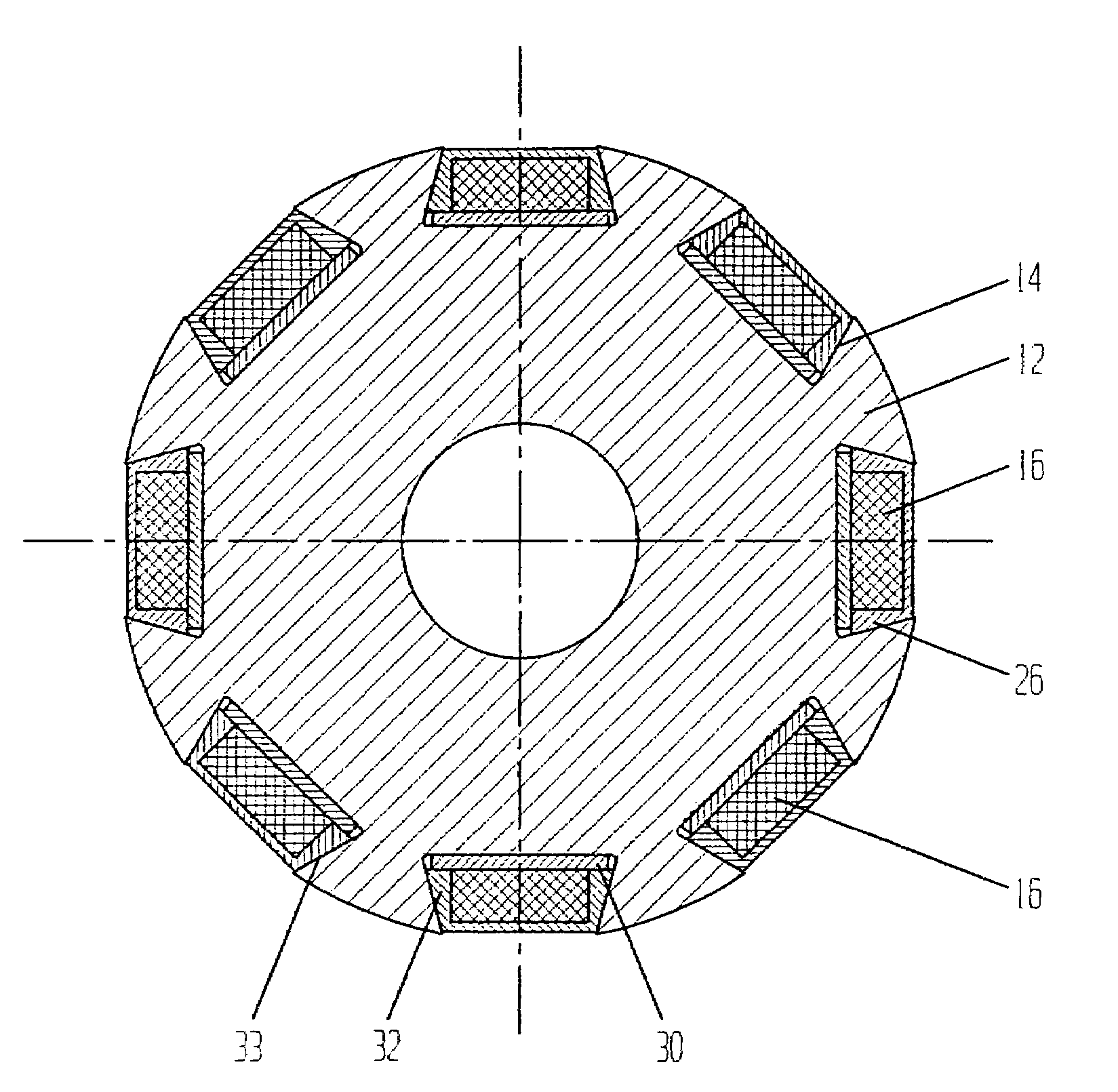
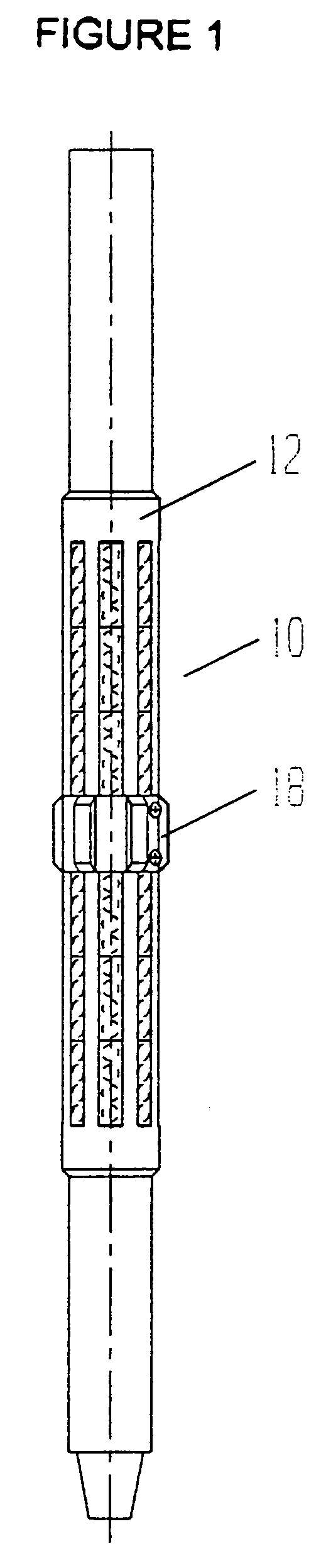
[0024]FIG. 1 depicts a magnetic tool according to one embodiment of the invention. The tool 10 includes an elongate tool body 12 which has circumferentially arranged slots 14 (see FIG. 4) each for receiving a plurality of magnets 16. With the embodiment pictured in FIG. 1, a centralizer 18 is provided near the central portion of the tool 10, and is spaced below a plurality of upper slots and above a plurality of lower slots.

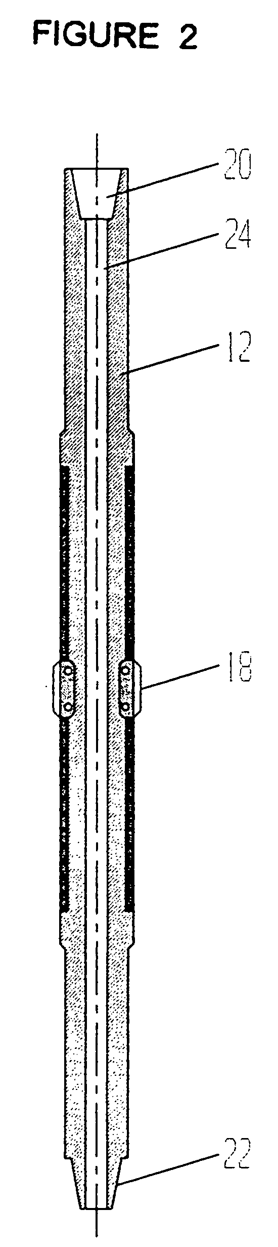
[0025]As shown more clearly in FIG. 2, a tool body 12 includes an upper box end 20 for threading the tool to a conventional running string, and a lower pin end 22 for attaching a continuation of the running string or another tool to the lower end of the tool body 12. A central bore 24 is provided through the tool body, and passes fluid from the string through the tool body for washing the well, which substantially contributes to an upward flow of debris and the collection of debris on the magnets.

[0026]The magnets may be provided in elongate carrier strips, and F...


PUM


Abstract

A tool 10 for suspending in a well retrieves various metal debris from the well, and includes an elongate tool body 12 within a plurality of circumferentially shaped slots 14. Each slot having a radially outward portion with a circumferential width less than a circumferential width of a radially inward portion. The plurality of magnets 16 are provided in each slot, and one or more stop rings 18 retain the plurality of magnets in the slots while allowing for removal of the magnets from the slots. Each of the plurality of magnets 16 may be substantially enclosed within a non-ferrous carrier 26 having an outer configuration for fitting within a respective of one of the plurality of slots. According to the method of invention, the magnets are postioned within the slots and are retained within the slots by the one or more stop rings, and the elongate tool body and the plurality of the magnets are suspended in a well.

Description

FIELD OF THE INVENTION[0001]The present invention relates to wellbore tools and methods for retrieving metal debris, such as cuttings and other metal objects, that may be formed by milling downhole objects, by unintentionally dropping an object in a wellbore, or by intentionally releasing a portion of a tool to fall in the well and subsequently be removed. More specifically, the tool of the present invention utilizes magnetic forces to attract ferrous metal debris, so that the tool effectively captures the debris and may then be retrieved to the surface from the wellbore.BACKGROUND OF THE INVENTION[0002]When drilling an oil or gas well, or when refurbishing an existing well, normal operations may result in various types of metal debris in a well. Downhole milling produces cuttings which often are not completely removed by circulation. Other metallic objects may drop into and collect near the bottom of the well, or on intermediate plugs placed within the well.[0003]Methods have been ...

Claims


Application Information

Patent Timeline
Patent Type & Authority Patents(United States)
IPC IPC(8): E21B37/00
CPCB08B9/0436E21B21/065E21B37/00
Inventor THERIOT, SR., CLAYTON
Owner BILCO TOOLS
Why Eureka
Try Eureka