Developing device used in image forming device

a technology of developing device and developing device, which is applied in the direction of electrographic process apparatus, instruments, optics, etc., can solve the problems of affecting the image quality of parts of the formed image, adverse effect of toner circulation, and drastic reduction of image quality, so as to achieve the effect of circulating the developer removed by the developing devi

Active Publication Date: 2007-05-22
BROTHER KOGYO KK
View PDF21 Cites 13 Cited by
  • Summary
  • Abstract
  • Description
  • Claims
  • Application Information

AI Technical Summary

Benefits of technology

[0007]In view of the foregoing, it is an object of the present invention to overcome the above problems and also to provide a developing device including a removing member that removes nonmagnetic single-component developer remaining on the surface of a developer-carrying member that was not supplied for developing an electrostatic latent image. It is another object of the present invention to provide an image-forming device including the developing device that can effectively circulate developer removed by the developing device.

Problems solved by technology

However, a problem caused by what is called sleeve ghosting can occur when some of the developer is not supplied to the image-carrying member for developing the electrostatic latent image and remains on the surface of the developer-carrying member after passing by the position opposing the image-carrying member.
However, in the device disclosed in Japanese unexamined patent application publication No.
Accordingly, toner removed by the removing member collects in a space between the removing member and a bottom surface of an outer case of the developing cartridge, which can have an adverse effect on toner circulation.
A worsening in toner circulation can lead to such problems as a drastic reduction in image quality in parts of the formed image.

Method used


Image

  • Developing device used in image forming device
  • Developing device used in image forming device
  • Developing device used in image forming device

Examples


first embodiment

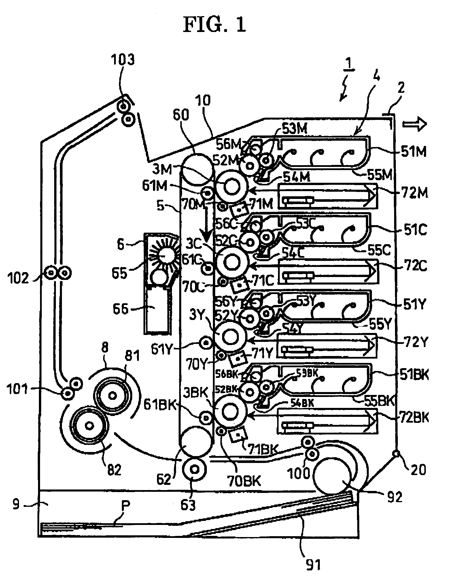
[0016]A developing device and an image-forming device according to preferred embodiments of the present invention will be described while referring to the accompanying drawings. the present invention will be described with reference to FIGS. 1 and 2. FIG. 1 is a side cross-sectional view showing the general construction of a color laser printer 1, which serves as the image-forming device to which the present invention is applied. The printer 1 shown in FIG. 1 includes a visible-image forming unit 4, a belt-shaped intermediate transfer member 5, a fixing unit 9, a paper supply unit 9, and a discharge tray 10.

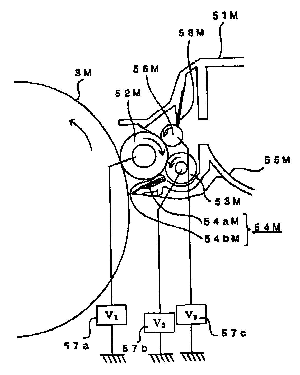
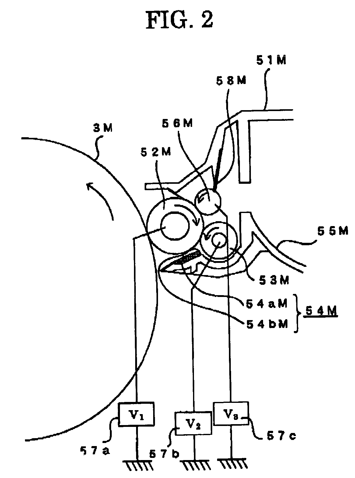
[0017]For each step in forming visible images with toner of the colors magenta (M), cyan (C), yellow (Y), and black (Bk), the visible-image forming unit 4 includes developing units 51M, 51C, 51Y, and 51Bk (collectively referred to as “developing units 51”), photosensitive drums 3M, 3C, 3Y, and 3Bk (collectively referred to as “photosensitive drums 3”), cleaning rollers 70M, 70C, ...

second embodiment

[0052]FIG. 3 is an enlarged view showing the relative parts of a developing unit 181M according to the present invention. The developing unit 151M can be applied to devices in which the photosensitive drum 3M rotates in the clockwise direction of the drawing. An image-forming device in which the photosensitive drum 3M rotates in this way can be easily understood by imagining the pickup roller 92 of the printer 1 in FIG. 1 being disposed on the left side of the drawing.

[0053]The developing unit 151M is provided with a developing roller 152M and a removing roller 156M disposed below the developing roller 152M. A supplying roller 153M and a thickness-regulating blade 154M are disposed in sequence downstream from the removing roller 156M in the rotational direction of the developing roller 152M. The constructions of the developing roller 152M, the supplying roller 153M, the thickness-regulating blade 154M, and the removing roller 156M are identical to the developing roller 52M, the supp...


PUM


Abstract

A developing device includes a removing roller positioned vertically above a supplying roller and in contact with a developing roller. Positively charged toner is supplied from the supplying roller to the developing roller and then supplied to a photosensitive drum for developing an electrostatic latent image thereon. Toner remaining on the developing roller that was not supplied to develop the latent image is removed by the removing roller. Some of the toner stripped by the removing roller falls down toward the supply roller and is again supplied to the developing roller.

Description

BACKGROUND OF THE INVENTION[0001]1. Field of the Invention[0002]The present invention relates to a developing device provided with a removing member that removes residual nonmagnetic single-component developer from a developer-carrying member, and an image-forming device including the developing device.[0003]2. Related Art[0004]One type of developing device well known in the art includes a developer-carrying member that develops an electrostatic latent image formed on an image-carrying member by supplying a charged nonmagnetic single-component developer to the surface of the image-carrying member, and a supplying member that supplies developer to the developer-carrying member. In this type of developing device, an image formation is performed in an electrophotographic method. That is, the supplying member supplies a nonmagnetic single-component developer, such as toner, accommodated in a toner-accommodating chamber or the like to the developer-carrying member while tribocharging the...

Claims


Application Information

Patent Timeline
Patent Type & Authority Patents(United States)
IPC IPC(8): G03G15/08G03G15/06
CPCG03G15/0808G03G15/0815G03G2215/0617
Inventor SATO, SHOUGO
Owner BROTHER KOGYO KK
Why Eureka
Try Eureka