Hydraulic control system for a dual wet clutch

a technology of hydraulic control system and wet clutch, which is applied in the direction of fluid actuated clutch, clutch, non-mechanical actuated clutch, etc., can solve the problems of complex production of gearboxes and unsatisfactory wet clutches, and achieve the effect of simple fashion and low energy consumption

Active Publication Date: 2017-09-21
VALEO EMBRAYAGES SAS
View PDF0 Cites 12 Cited by
  • Summary
  • Abstract
  • Description
  • Claims
  • Application Information

AI Technical Summary

Benefits of technology

[0010]An idea on which the invention is based is to eliminate the disadvantages of the existing art by proposing a dual wet clutch that offers low energy consumption and ensures cooling of the clutches in simple fashion.
[0016]A hydraulic control system of this kind therefore does not require the presence of dynamic seals, which allows the drag torque, and consequently the energy consumption of the engine, to be limited.
[0017]The cooling circuit for the clutches is moreover integrated into the hydraulic control system of the dual clutch, so that the number of components of the dual wet clutch can be reduced and its size can be decreased; this also contributes to an increase in standardization of its components.
[0018]Lastly, circulation of the cooling fluid is particularly efficient because of the appropriate axial positioning of the output orifice, which allows effective cooling of the dual clutch to be provided. In particular, because the cooling fluid flow conduit opens beyond the travel of the annular pistons between their active position and inactive position, efficient cooling of the clutches is ensured regardless of the position of the clutches and, in particular, when they are positioned at the biting point and the cooling requirements are therefore greatest.
[0021]According to an embodiment, the internal tube has a plurality of cooling fluid flow conduits distributed circumferentially around the axis X, which allows efficient and homogeneous cooling to be ensured. According to an embodiment, the cooling fluid flow conduits are evenly distributed around the axis X.
[0036]According to an embodiment, the input disc carriers of the two clutches are fastened to one another and are mounted rotatingly around the axis X on the internal tube of the hydraulic control system thanks to a bearing. Because the input disc carriers are supported on the control system, which is intended to be fastened onto the gearbox, the bearing is therefore mounted on a stable and rigid element that is not subject to axial and / or radial deflections, which ensures that the dual clutch is stable and the bearing is more reliable. In addition, since the bearing is mounted on an internal tube having a relatively small diameter, the diameter of the bearing is limited; this allows its cost to be reduced, in particular if it is a rolling bearing.

Problems solved by technology

A dual clutch of this kind is not entirely satisfactory, since the presence of dynamic seals has the effect of generating friction that induces a drag torque which is responsible for excessive energy consumption.
The fluid intended for cooling of the clutches is supplied, however, through one of the input shafts of the gearbox, which makes production of the gearbox more complex.

Method used


Image

  • Hydraulic control system for a dual wet clutch
  • Hydraulic control system for a dual wet clutch
  • Hydraulic control system for a dual wet clutch

Examples


Embodiment Construction

)

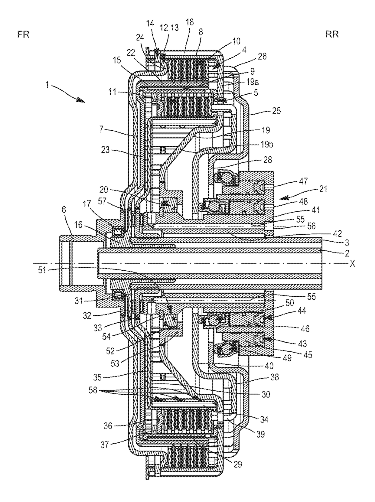
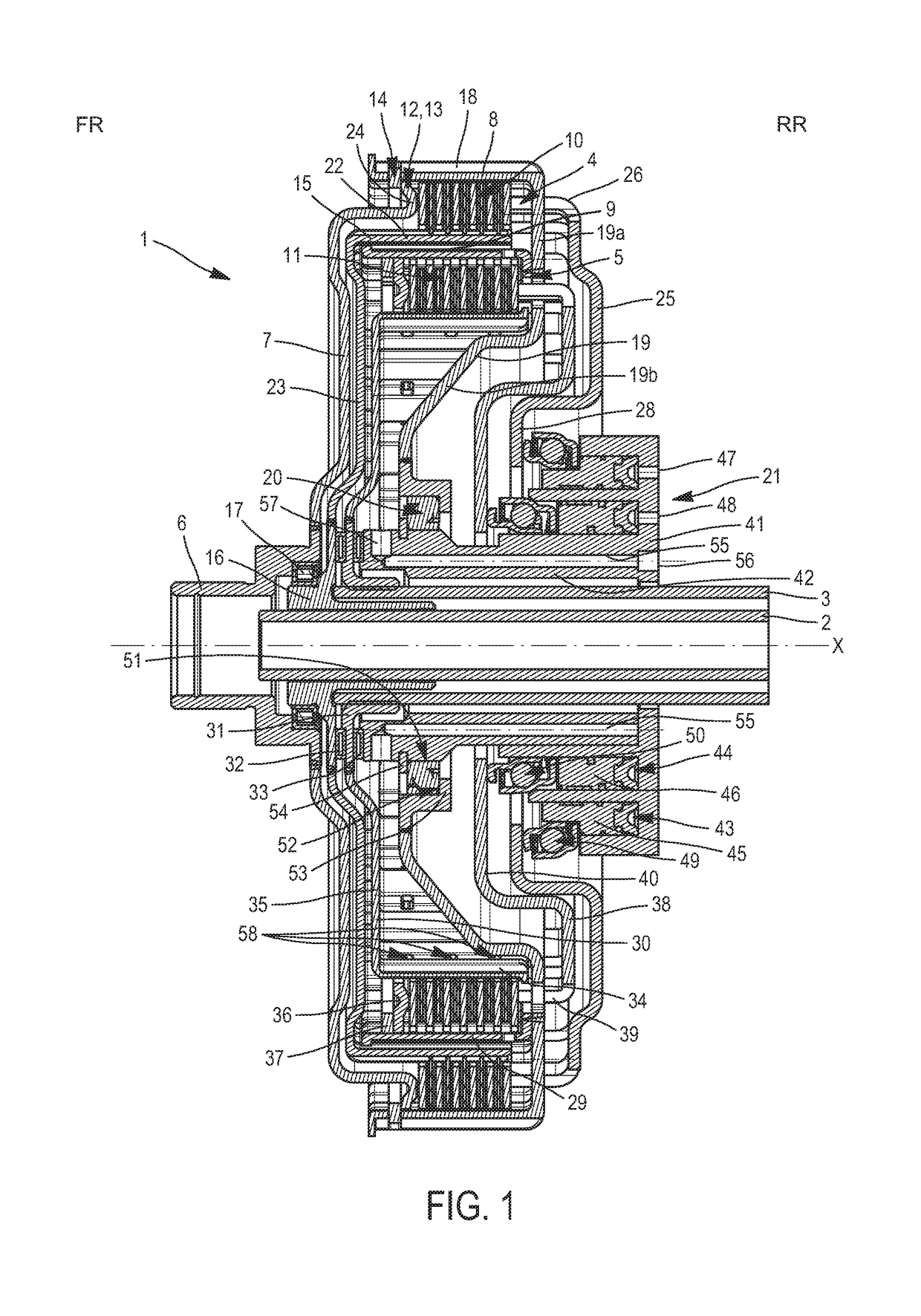
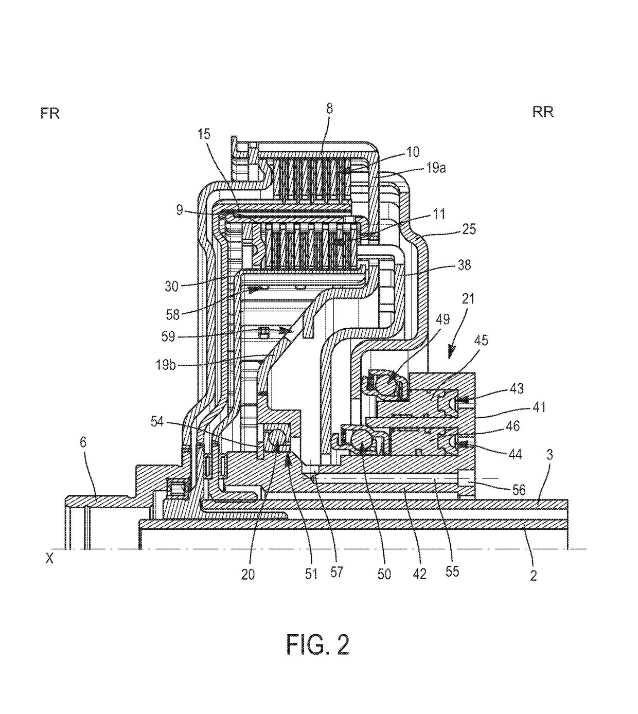
[0053]In the description and the claims, the terms “outer” and “inner,” as well as the orientations “axial” and “radial,” will be used to designate elements of the dual clutch in accordance with the definitions given in the description. By convention, the “radial” orientation is directed orthogonally to rotation axis X of the dual clutch which determines the “axial” orientation; and, moving away from said axis from inside to outside, the “circumferential” orientation is directed orthogonally to axis X and orthogonally to the radial direction. The terms “outer” and “inner” are used to define the relative position of one element with respect to another with reference to axis X; an element close to axis X is thus referred to as “inner” as opposed to an “outer” element arranged radially at the periphery. In addition, the terms “rear” (RR) and “front” (FR) are used to define the relative position of one element with respect to another along the axial direction; an element intended to be...


PUM


Abstract

The invention relates to a hydraulic control system (21) for a dual wet clutch (1), having:housing (41) having an internal tube (42) extending axially around the axis X and configuring an internal space intended for passage of the two input shafts (2, 3) of a gearbox, and a first and a second annular chamber (43, 44) concentric around the axis X and disposed radially around the internal tube (42);a first and a second annular piston (45, 46), which are respectively mounted axially slidingly inside the first and the second annular chamber (43, 44), the first and the second annular piston (45, 46) each carrying a rotating stop (49, 50);the internal tube (42) having at least one flow conduit (55) for a cooling fluid, intended to direct the cooling fluid to the clutches (4, 5).

Description

CROSS-REFERENCE TO RELATED APPLICATIONS AND CLAIM TO PRIORITY[0001]This application is related to Patent Application No. 1652224 filed Mar. 16, 2016 in France, the disclosure of which is incorporated herein by reference and to which priority is claimed.FIELD OF THE INVENTION[0002]The invention relates to the field of motor vehicle transmissions.[0003]The invention relates more specifically to a dual wet clutch intended to be disposed in a transmission drivetrain of a motor vehicle between an engine unit and a gearbox comprising two input shafts.BACKGROUND OF THE INVENTION[0004]A dual wet clutch has an input hub intended to be rotationally integrated with an engine flywheel fastened to the crankshaft of the engine, and two clutches each having an input disc carrier rotationally connected to the input hub, an output disc carrier rotationally connected to one or the other of the two input shafts of a gearbox, and a multiple-disc assemblage that is intended to transmit a torque between ...

Claims


Application Information

Patent Timeline
Patent Type & Authority Applications(United States)
IPC IPC(8): F16D13/72F16D25/12F16D25/0638F16D25/10F16D13/52F16D21/06
CPCF16D13/72F16D13/52F16D21/06F16D2021/0661F16D25/10F16D25/123F16D25/0638F16D13/70F16D25/082F16D2300/0214F16D13/385
Inventor DOLE, ARNAUDTHIBAUT, FRANCOIS
Owner VALEO EMBRAYAGES SAS
Why Eureka
Try Eureka