Dehumidifier System Device and Method

a dehumidifier and system technology, applied in the direction of defrosting, heating types, domestic cooling devices, etc., can solve the problems of large devices and systems, inconvenient dehumidification of small enclosures and containers, and loss of beneficial levels of humidity needed for good health, etc., to achieve rapid removal of moisture, improve efficiency, and reduce the effect of heat loss

Inactive Publication Date: 2008-11-20
SHALOM LEVIN
View PDF7 Cites 13 Cited by
  • Summary
  • Abstract
  • Description
  • Claims
  • Application Information

AI Technical Summary

Benefits of technology

[0014]The dehumidifier device of the present invention comprises a condensation unit, typically a thermoelectric element with a moisture collector, and a sealed pump, such as peristaltic pump, which pumps the condensed humidity out of the sealed enclosure, yet maintains the enclosure sealing. The system is provided with a controller which alternately activates the thermoelectric element and the pump, either continuously, periodically, or in accordance with a humidity or relative humidity sensor. Optionally, in large-volume enclosures and containers, a fan assembly is connected to the controller so as to provide for more efficient circulation of the air since it is desirable to have a more rapid removal of moisture.
[0015]The device is particularly useful in keeping a dry environment in enclosures where humidity can damage such items as elect...

Problems solved by technology

Gas-heated systems are also common in homes and offices and in places where the undesirable effect of the drying of the heated air results in loss of beneficial levels of humidity needed for good health.
Most such devices and systems are large and thus not well-suited for dehumidification of small enclosures and containers.
There are several problems with the above-mentioned devices and systems.
Another problem is that nitrogen filled cont...

Method used


Image

  • Dehumidifier System Device and Method
  • Dehumidifier System Device and Method
  • Dehumidifier System Device and Method

Examples


Embodiment Construction

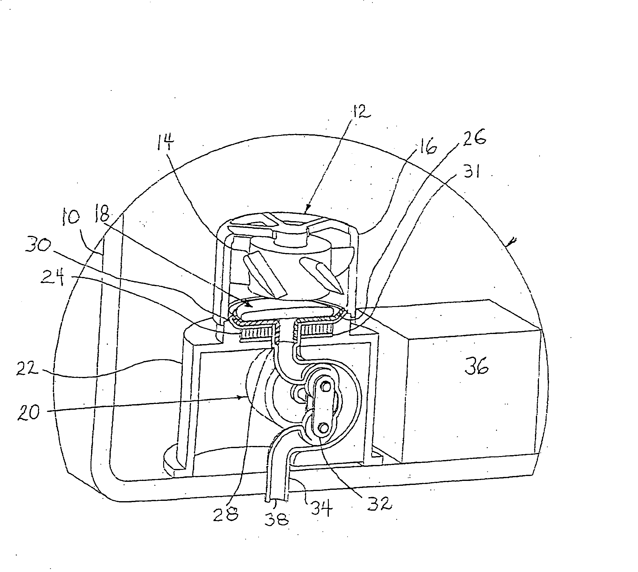
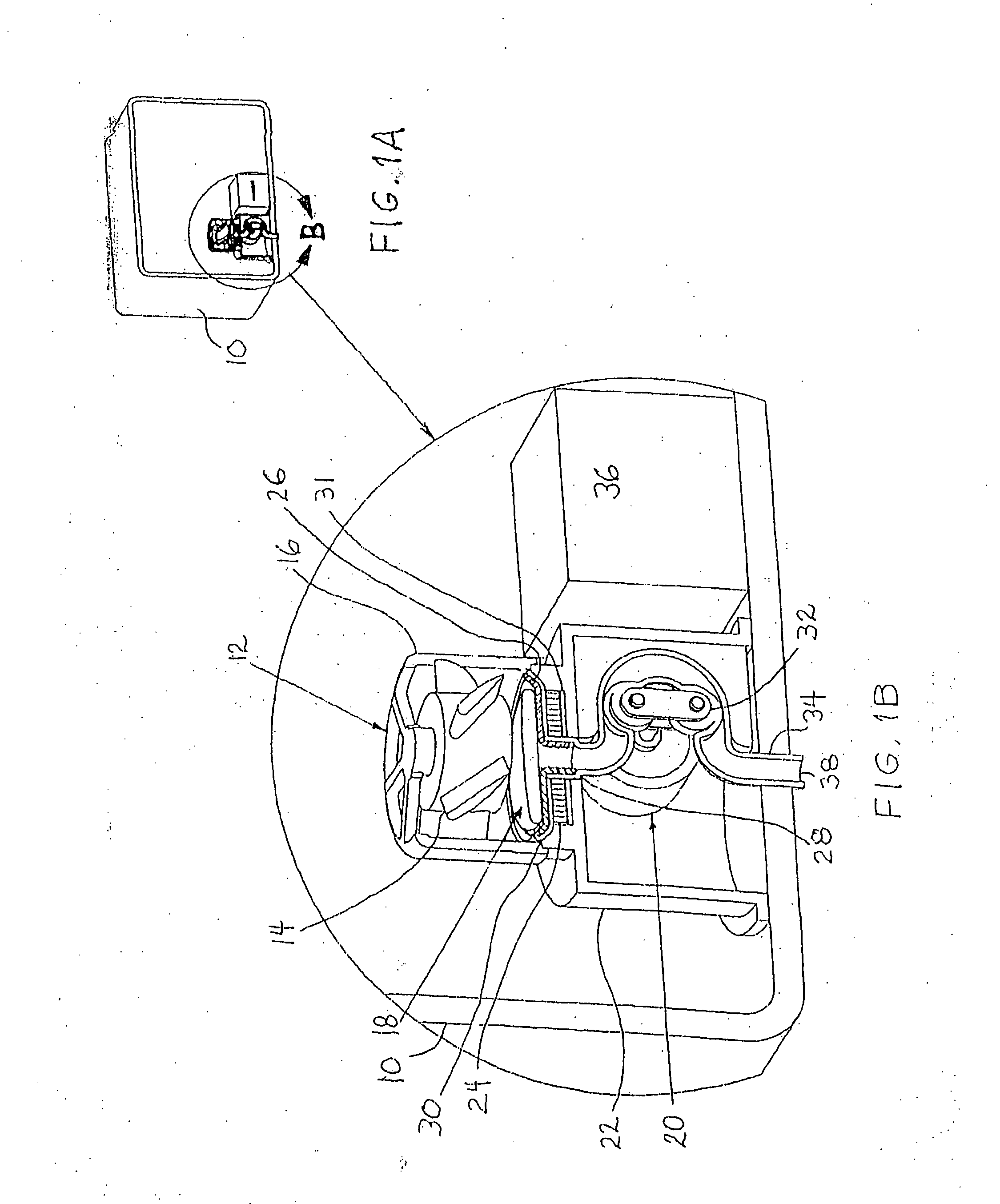
[0023]FIG. 1A is a general, cross-section view of the system of the invention in accordance with a preferred embodiment thereof. FIG. 1A shows an enclosure 10 where it is desired to maintain a dry environment and indicates a view B of the device of the invention internally mounted in enclosure 10.

[0024]FIG. 1B is an enlarged, detailed view of the invention from FIG. 1A.

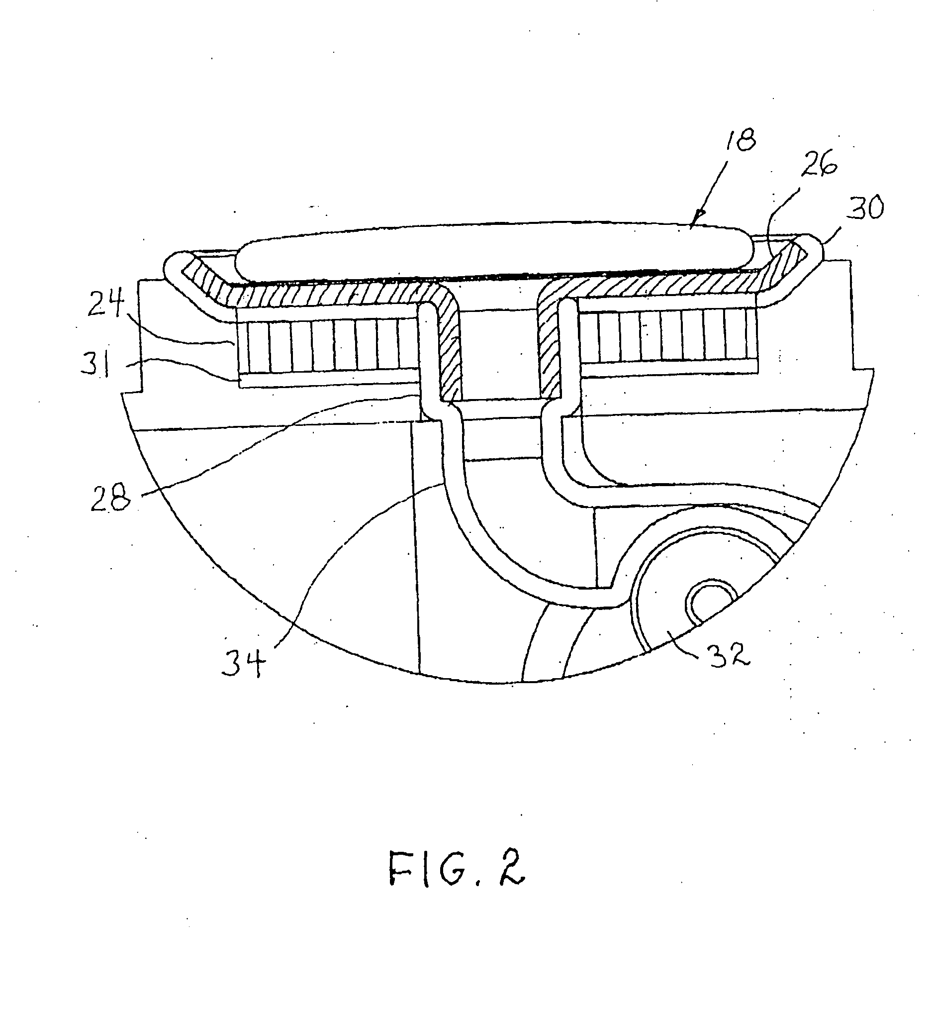
[0025]In a preferred embodiment of the invention, the dehumidifier system comprises a fan assembly 12, having a propeller 14 mounted inside a propeller housing 16, a condenser unit 18, a pump unit 20, and a pump housing 22. Condenser unit 18 comprises a thermoelectric element 24 provided with a central moisture collector 26 (indicated with hatch lines) formed with a funnel 28. Collector 26 and funnel 28 are typically made of stainless steel. Collector 26 is attached to thermoelectric element 24 utilizing a heat-conducting grease. An isolator hub 30), positioned in close proximity to collector 26, isolates the cold sur...


PUM


Abstract

A dehumidifier system and device for maintaining a dry air environment in enclosures by extracting the water to outside the enclosure. The dehumidifier device comprises a condensation unit, typically a thermoelectric clement with a moisture collector, and a sealed pump, such as peristaltic pump, which pumps the condensed humidity out of the sealed enclosure, yet maintains the enclosure seal. The system is provided with a controller which alternately activates the thermoelectric element and the pump, in at least one mode: continuous, periodical, and programmable utilizing a humidity/relative humidity sensor. Optionally, in large-volume enclosures and containers, a fan assembly is connected to the controller so as to provide for rapid circulation of the air and removal of moisture.

Description

FIELD OF THE INVENTION[0001]The present invention relates generally to dehumidifier systems and devices, and more particularly to a dehumidifier system device and method for active water extraction from small enclosures and containers to a space external thereto.BACKGROUND OF THE INVENTION[0002]Dehumidifier systems and devices are in widespread use today, especially in buildings, storage centers, and other sites where active central-air conditioning systems are installed. Gas-heated systems are also common in homes and offices and in places where the undesirable effect of the drying of the heated air results in loss of beneficial levels of humidity needed for good health. Most such devices and systems are large and thus not well-suited for dehumidification of small enclosures and containers.[0003]For these latter applications, a passive system is generally employed utilizing chemicals in powder or gel form, such as silica-gel or other hydrophobic materials which are introduced to ab...

Claims


Application Information

Patent Timeline
IPC IPC(8): F25B21/02F25B21/00F24F3/14F24F5/00F24F13/22
CPCF24F3/14F24F5/0042F24F13/222F24F2003/1446F24F2006/125Y02B30/80Y02B30/70
Inventor SHALOM, LEVIN
Owner SHALOM LEVIN
Why Eureka
Try Eureka