Backrest of an automobile vehicle seat

Active Publication Date: 2007-05-29
FAURECIA
View PDF18 Cites 86 Cited by
  • Summary
  • Abstract
  • Description
  • Claims
  • Application Information

AI Technical Summary

Benefits of technology

[0014]Another advantage of the invention is that, due to the fact that the shield frame is concealed, as covered by the cover when the backrest padding is completed, the said shield frame can be made of all recycled plastic materials or any other material such as for example glass fibre reinforced resin or compacted wood, etc., its appearance having no importance for the aesthetic appearance of the finished seat unlike prior art where a plastic shell is used and remains visible on the finished seat.
[0015]From the manufacturing process and seat assembly point of view, the use of the shield frame allows the padding to be simplified concerning the installation both of the rear screen and of the cover covering the front and the sides of the backrest. The cover and the screen are attached directly to the shield frame with full accessibility to the attachment means from the exterior. There are therefore no longer any attachment or hooking operations required on the framework and/or the suspension mat, obliging the operator to make, as in prior art, hooking operations from the bottom of the cover or the screen at the same time as the adjustment of these items on the backrest. Also, the number of attaching parts can be significantly reduced.
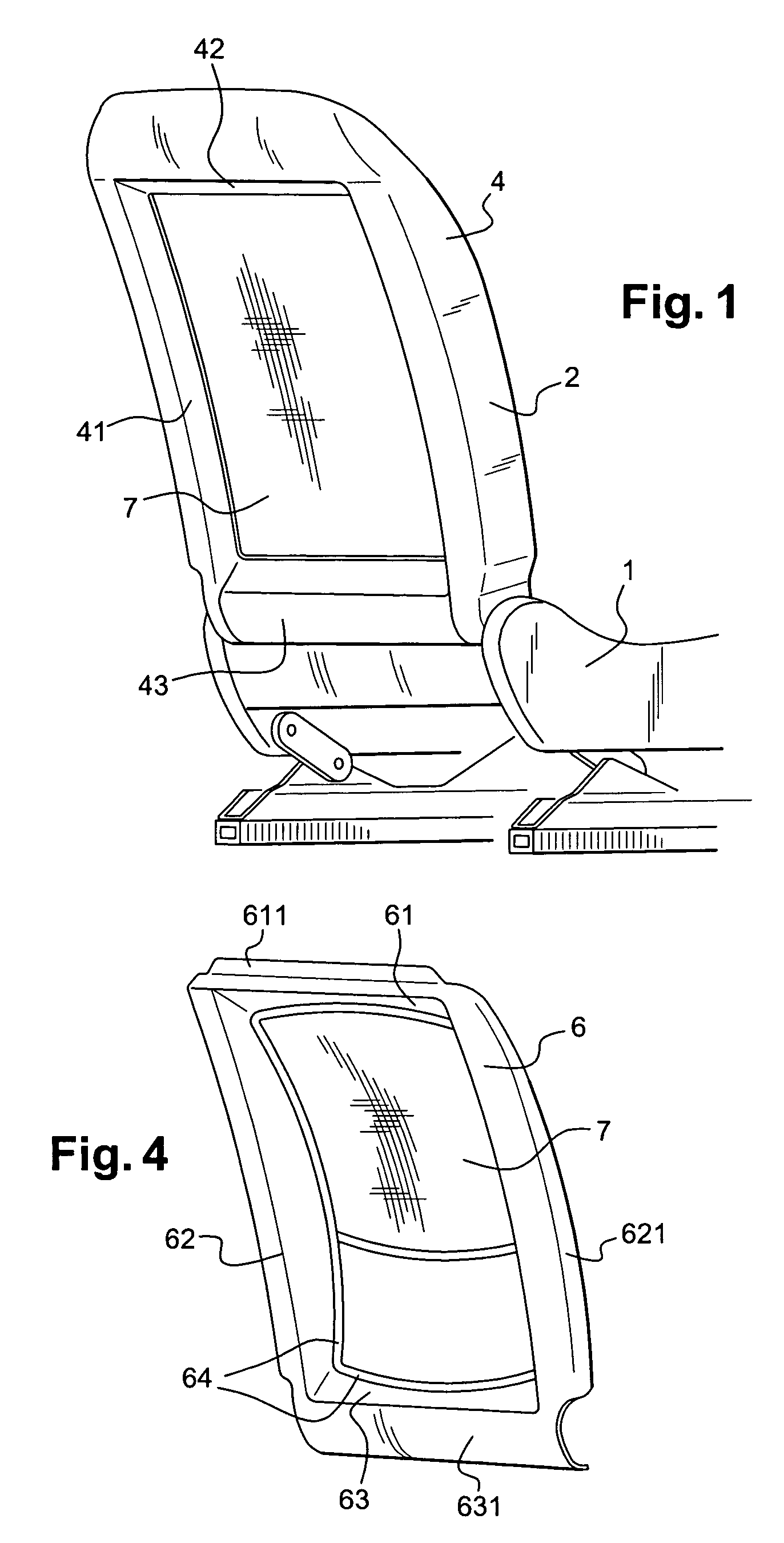
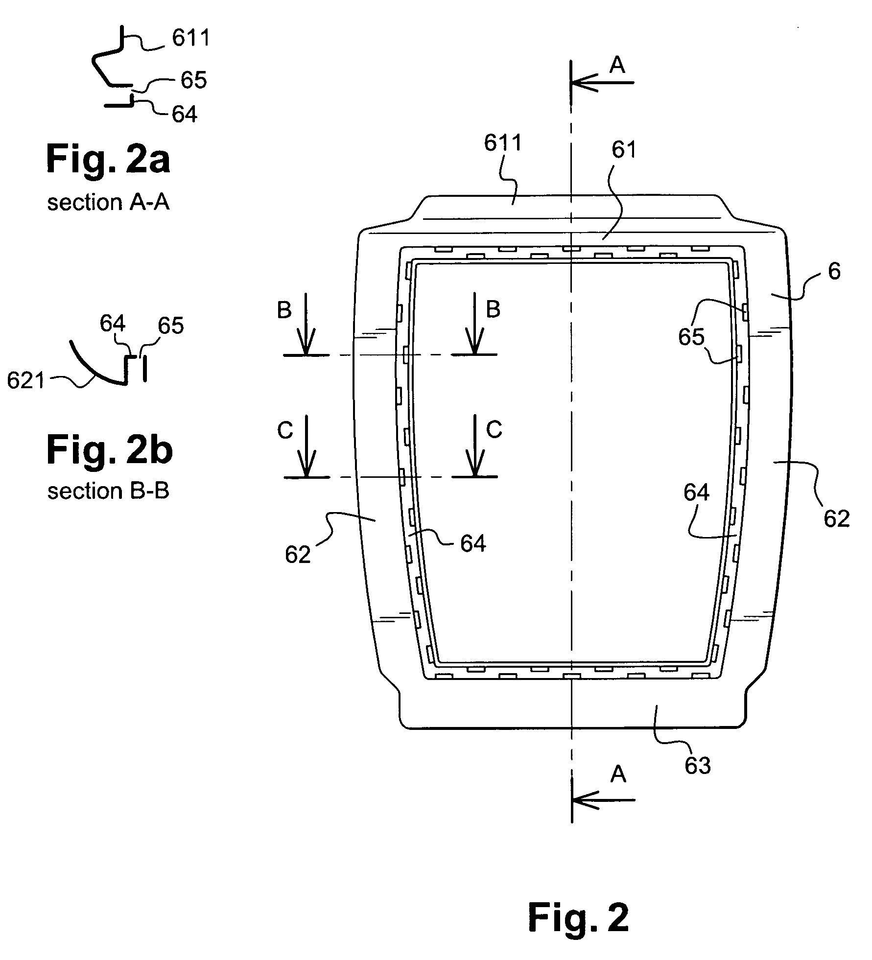
[0016]According to a preferential arrangement, the shield frame is a closed frame and includes four sides, the groove running continually around the

Problems solved by technology

With this first embodiment with a flexible textile screen, it is difficult to ensure good attachment quality especially in the finishing zones at the bottom of the backrest and, in addition, installation requires many attachment parts such as fasteners, tie-downs, etc.
The appearance and the stiffness of these shells do not allow market requir

Method used


Image

  • Backrest of an automobile vehicle seat
  • Backrest of an automobile vehicle seat
  • Backrest of an automobile vehicle seat

Examples


Embodiment Construction

[0036]The seat shown on FIG. 1 includes a seat pan 1 and a backrest 2, in compliance with the invention, hinged on the seat pan.

[0037]The backrest includes, as it can especially be seen on FIGS. 3 and 6, a metallic framework 21, consisting, for example, of a bent tube forming an upper crossmember 23, two lateral uprights 22 and a lower crossmember 24. The lower ends of the lateral uprights, which extend downwards beyond the lower crossmember, accommodate the backrest-to-seat pan hinge mechanisms 25.

[0038]A suspension mat 26 is attached to the framework 21, in a manner known per-se. The mat 26 supports a padding 3 covered by padding cover 4.

[0039]In the example shown, the cover and padding assembly forms one piece obtained either by a known in-situ type process, where the padding is a synthetic foam cured in a mould directly in contact with the cover, or by bonding of the cover to the previously formed padding according to typical processes also known. As it can be seen on FIG. 5, th...


PUM


Abstract

The backrest (2) of an automobile vehicle seat includes a framework (21), a padding (3), a padding cover (4) covering the front face and the sides of the backrest and a padding screen (7) for the rear face of the backrest. It includes a rigid back panel shield frame (6) with at least two lateral sides (62) and a bottom side (63), the said shield frame being adapted to be attached to the framework (21) of the backrest to cover the lateral edges of the framework and a bottom part of the rear of the backrest, the shield frame (6) including towards an inner edge at least one groove (64) adapted to accommodate and hold an edge (44) of the cover and an edge (71) of the screen, the said cover covering the shield frame.

Description

FIELD OF THE INVENTION[0001]This invention concerns a backrest of a seat especially for automobile vehicles.[0002]More precisely, it concerns the padding and the finishing of the rear of the backrest, especially for so-called thin-type or reduced volume seat backrests. The aim of this type of seat, in the first row, or possibly any other row, is especially to allow the padding to be placed as near as possible to the technical zones, that is zones including functional structural elements such as framework elements or a suspension mat for example or mechanisms or equipment such as hinge mechanisms, inflatable protective cushions, etc. Apart from creating special style effects, the aim is thus to optimise passenger comfort in the seats located behind the concerned seats by pushing the rear face of the backrest as far as possible forwards whilst complying with the shapes and comfort elements required for the front face of the backrest. The invention could however apply also to any other...

Claims


Application Information

Patent Timeline
IPC IPC(8): B60N2/42B60N2/58B60N2/68B60N2/70
CPCB60N2/70B60N2/6009B60N2/5825
Inventor PHILIPPOT, JEROMEDELIAS, PHILIPPE
Owner FAURECIA
Why Eureka
Try Eureka