Molded piezoelectric apparatus

a piezoelectric and molded technology, applied in piezoelectric/electrostrictive transducers, generators/motors, mechanical vibration separation, etc., can solve the problems of increasing manufacturing costs, maintaining certain mechanical tolerances for all parts, and abrasion on both sides, so as to achieve a wide range of shapes and surface finishes, the effect of mass production processes and efficient mass production

Active Publication Date: 2007-05-29
ELLIPTEC RESONANT ACTUATOR
View PDF36 Cites 9 Cited by
  • Summary
  • Abstract
  • Description
  • Claims
  • Application Information

AI Technical Summary

Benefits of technology

[0009]Polymers have an advantage over metals in that some can be processed in a liquid or near-liquid form at lower temperatures, or in that some are processed as separate chemical compounds that react to form the polymer at the time of manufacture. Polymers are easily combined with other materials to form composites. Both pure polymers and their composites will be referred to as polymeric compounds for simplicity. While polymers can be processed using injection molding or similar, metals and their composites are typically processed using die-casting or similar. For the purpose of the present invention, however, these terms will be used interchangeably as the both refer to a method to shape a material using some form of mold although a complete mold may not be necessary if the processed compound is sufficiently viscous.
[0010]As a compound, which initially can be liquid, powdery, etc., hardens inside the mold, it can develop an intrinsic urge to contract, expand, or deform otherwise. Instead of being an undesired side effect, this effect is purposefully exploited in the present invention to place a piezoelectric element in compression inside a piezoelectric apparatus while concurrently forming at least a portion of the apparatus.
[0011]A further advantage of injection molding of polymers and die casting of metals is that they are efficient mass production processes that offer a broad range of shapes and surface finishes.
[0016]In a preferred embodiment, the carrier comprises an insert that is continuously connected to the piezoelectric element by the compound and provides additional functionality.
[0019]In another preferred variation of the method, the piezoelectric element is held in place during molding by electrical connections to the piezoelectric element through which an electrical signal may be applied during the manufacture of the system. The compound is preferably selected to maximize the transmission of mechanical vibrations from the piezoelectric element into the carrier when the piezoelectric element is excited with a vibratory electric signal. It is possible to cause the static preload on the piezoelectric element by electrically polarizing the piezoelectric element.

Problems solved by technology

The need for assembling the one or more bolts is a drawback of the method and apparatus as this assembly step and required hardware typically increases manufacturing costs.
The need for maintaining certain mechanical tolerances for all the parts involved is a drawback of this method.
Also, the process of inserting the piezoelectric element into the opening can pose difficulties as it may lead to scraping or abrasion on both the piezoelectric element and the inside of the opening.
Also, the forces necessary to insert the piezoelectric element may damage it.
Furthermore, the interposed polymer does not completely separate the piezoelectric element from the part holding the piezoelectric element in compression.

Method used


Image

  • Molded piezoelectric apparatus
  • Molded piezoelectric apparatus
  • Molded piezoelectric apparatus

Examples


Embodiment Construction

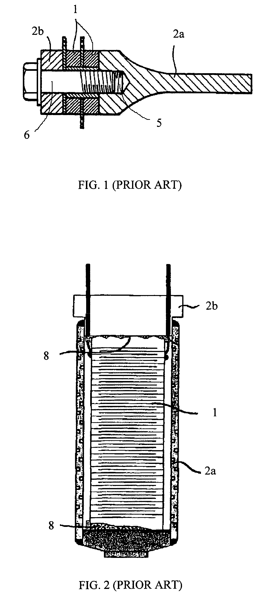
[0045]Referring to FIG. 1, this invention relates to piezoelectric devices 7 that comprise at least a piezoelectric element 1 and a carrier 2 to hold the piezoelectric element 1 in static compression to prevent damage to the piezoelectric element 1 due to tensile forces during operation of the device 7, which is a particularly important issue if the piezoelectric element 1 has a multilayer construction. In the description that follows and in the associated figures, like numbers refer to like parts and features throughout.

[0046]FIG. 1 exemplifies a typical prior art piezoelectric apparatus as disclosed in U.S. Pat. No. 4,728,843, wherein a piezoelectric element 1 is held in static compression by fastening a threaded bolt 6 that extends through a threaded hole 5 in a carrier 2. In the case shown, the carrier 2 is divided into portions 2a and 2b and the piezoelectric element 1 has a through hole for the bolt 6. The method of placing a piezoelectric element 1 in compression using a bolt...


PUM

PropertyMeasurementUnit
temperatureaaaaaaaaaa
temperaturesaaaaaaaaaa

Abstract

A piezoelectric apparatus comprising a piezoelectric element that is held in static compression is manufactured using moldable materials and a molding process, e.g., injection molding or die casting. The static compression is caused by an intrinsic urge of the moldable material to expand, contract, or deform otherwise, which develops in the material during the hardening phase of the molding process. To enhance the usefulness of the device, a variety of inserts can be connected to the device and various features can be formed by the moldable material at the same time as the molding process takes place. Static preloads may also be caused by mechanically preloaded elements that are introduced during the molding process or by elements that concurrently introduced but that are permanently deformed thereafter.

Description

FIELD OF INVENTION[0001]This invention relates to a piezoelectric apparatus that is manufactured using injection molding and die-cast principles and preferably polymeric compounds to place a piezoelectric element in compression within the piezoelectric apparatus.BACKGROUND OF THE INVENTION[0002]In a typical piezoelectric apparatus, a piezoelectric element is mechanically connected to another part, such as a mechanical resonator, to transmit vibratory motion into that part when an appropriate electrical signal is applied to the piezoelectric element. Such a piezoelectric apparatus generally falls into one of two categories. In the first category, the piezoelectric element is placed in static compression along the principal axis of piezoelectric action by a mechanical preload in order to prevent potentially damaging tensile forces on the piezoelectric element during operation of the apparatus. In the second category, such a preload is not necessary. An apparatus comprising a multilaye...

Claims


Application Information

Patent Timeline
Patent Type & Authority Patents(United States)
IPC IPC(8): H01L41/08B06B1/06H01L41/053H01L41/09H01L41/22
CPCY10T29/42H10N30/886H10N30/202H10N30/02
Inventor MAGNUSSEN, BJOERNVARADI, PETER C.
Owner ELLIPTEC RESONANT ACTUATOR
Why Eureka
Try Eureka