

Mud flap mounting system and method for use thereof
a mounting system and mud flap technology, applied in the field of mud flap mounting system, can solve the problems of destroying the mud flap and bending the mounting bracket, and achieve the effect of reducing repair and downtime costs
- Summary
- Abstract
- Description
- Claims
- Application Information
AI Technical Summary
Benefits of technology
Problems solved by technology
Method used
Image

Examples
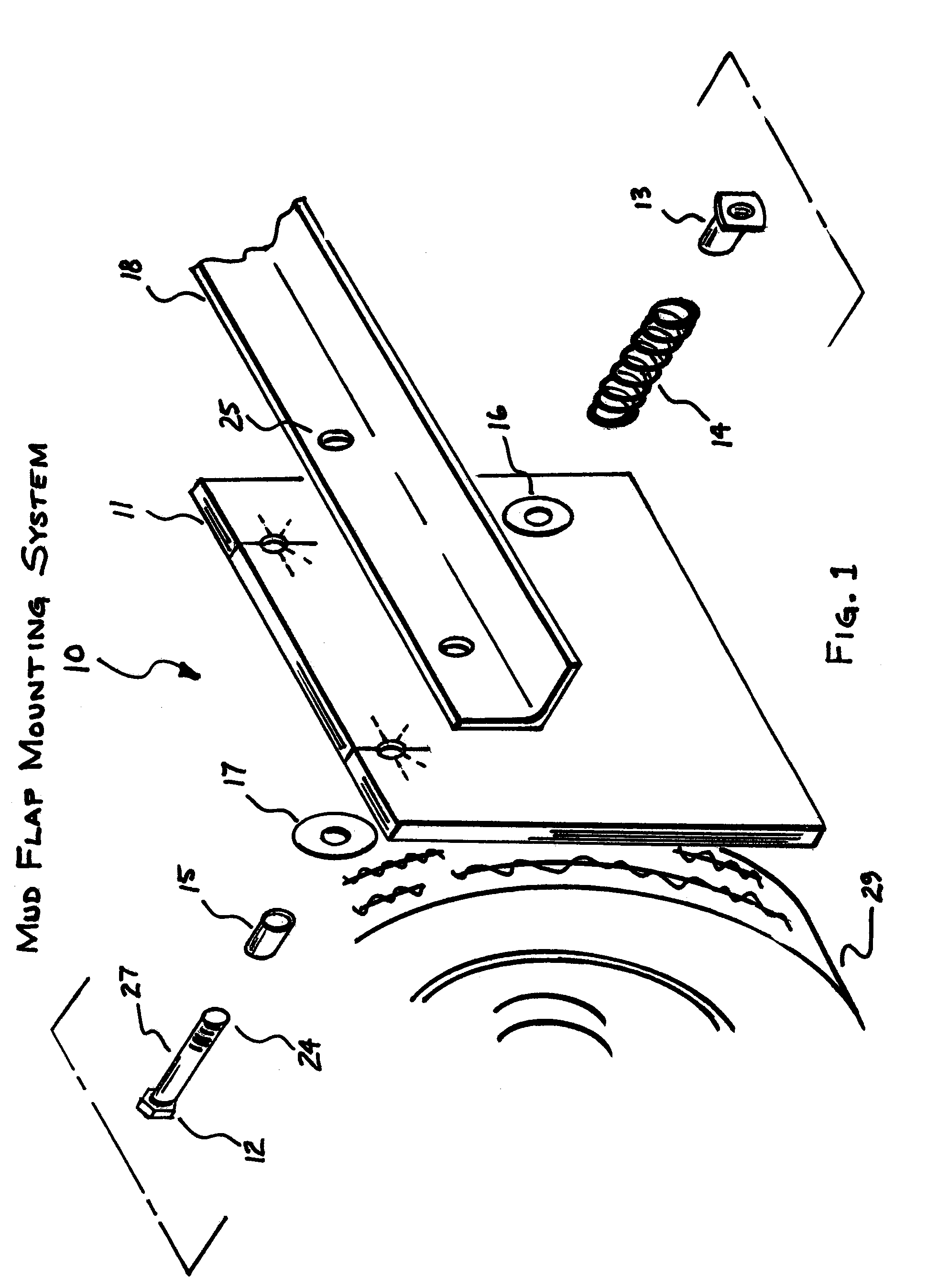
first embodiment
Operation—First Embodiment
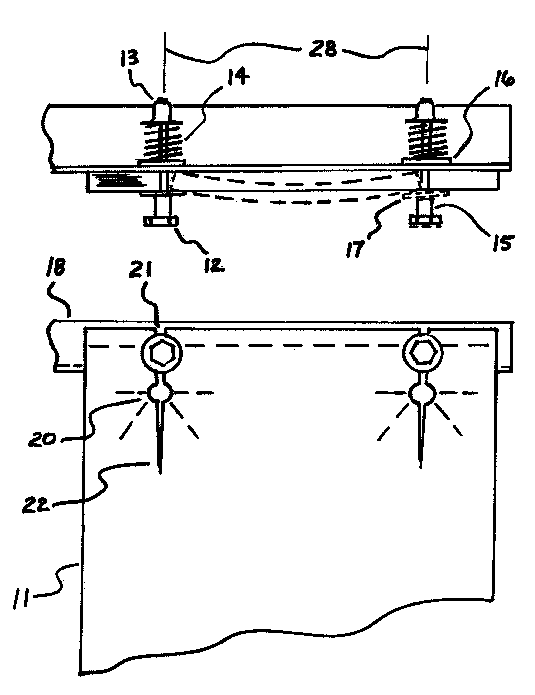
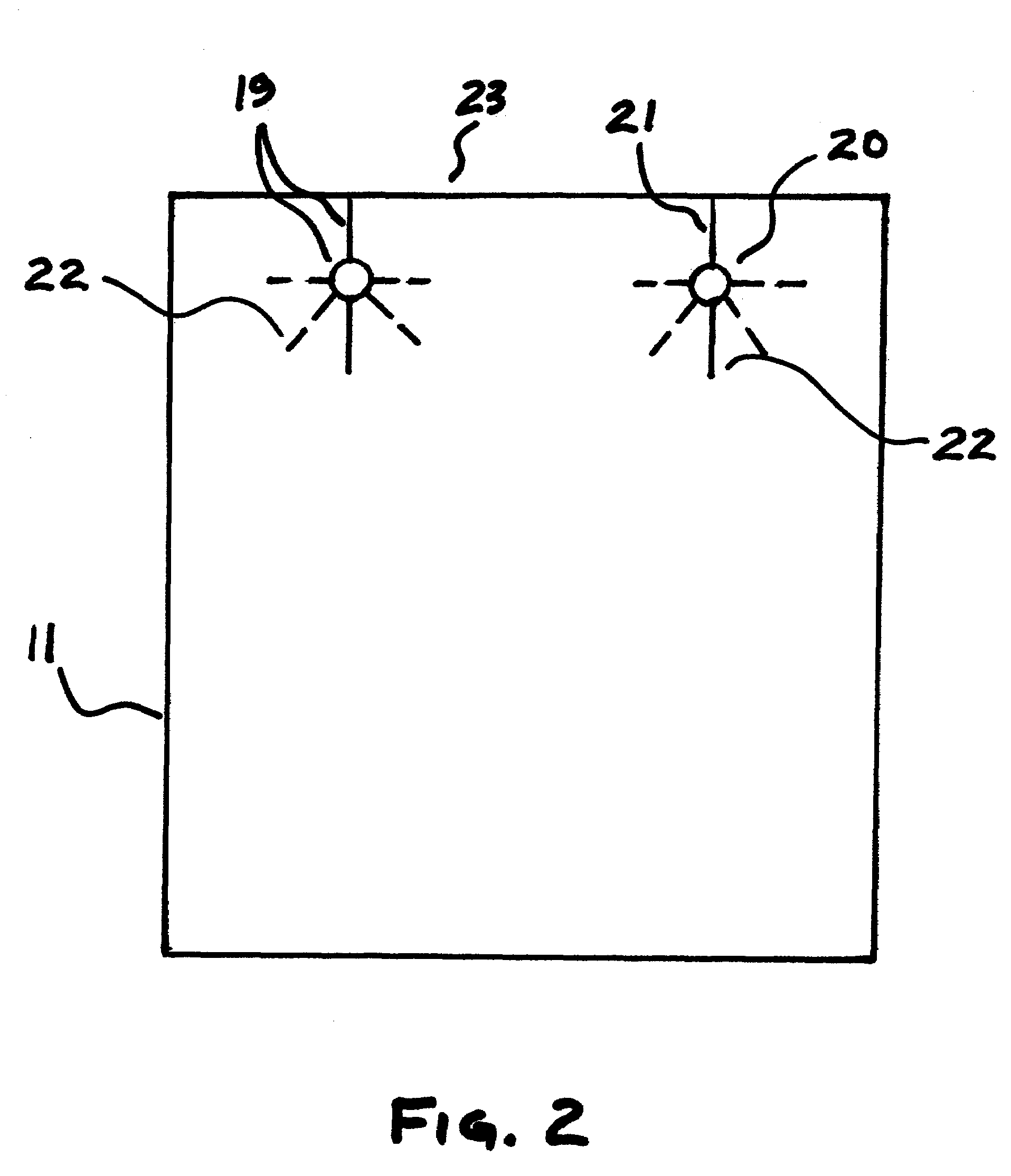
[0026]Referring to FIGS. 1 and 3, the dynamics of the releaseability function for the first Embodiment of the Mud Flap Mounting Systems 10 is as follows: The pressure of spring members 14 indirectly holds the mud flap 11 in a substantially flat vertical plane against mounting bracket 18 and prevents the tightening members 13 from unloosening during service. When the mud flap 11 is pinched between a rotating tire 29 and a curb or other obstruction while backing up the vehicle, the resultant extremely high instantaneous jerk on mud flap 11 causes the shank 27 of the mounting bolts 12 to act as a cam to spread the mud flap 11 slits 21 and 22 apart, distorting the mud flap 11 within the spaces 28 between the bolt holes 20, creating a retreating axial movement of Pressure Plates 17 and bolts 12 to release the mud flap 11 from its mounting bracket 18. To remount mud flap 11, the tightening members 13 are unscrewed by hand, without the aid of tools. Spring members...
second embodiment
Operation—Second Embodiment
[0028]Referring to FIGS. 4 and 6, the dynamics of the releaseability function for the Second Embodiment of Mud Flap Mounting System 50 is as follows: The force of spring members 54 hold the mud flap 51 in a substantially flat vertical plane against the mounting bracket 18 during service. When mud flap 51 is pinched between a rotating tire 29 and a curb or other obstruction while backing up the vehicle, the extremely high instantaneous jerk on the mud flap 51 causes the mud flap 51 to be pulled past the bolts 12 which releases the mud flap 51 from its mounting bracket. To remount mud flap 51, the tightening members 13 are loosened with tools to release spring member 54 pressure, allowing replacement of mud flap 51 on the mounting bracket 18. The tightening members 13 are then adjusted with tools' to compress the spring members 14 to their originally setting.
Other Applications
[0029]Referring to FIGS. 7A, 7B, 8A and 8B, there is shown two other typical applic...
PUM
 Abstract
Description
Claims
Application Information