Control device for hybrid vehicle

a control device and hybrid technology, applied in the direction of motor/generator/converter stopper, dynamo-electric converter control, machine/engine, etc., can solve the problems of increased shock of change and inability to perform smooth change, and achieve smooth shift, reduce the difference between the revolution speed and the effect of smooth shifting

Inactive Publication Date: 2007-06-05
SUBARU CORP
View PDF13 Cites 22 Cited by
  • Summary
  • Abstract
  • Description
  • Claims
  • Application Information

AI Technical Summary

Benefits of technology

[0006]An object of the present invention is to prevent occurrence of a change shock caused in shifting the vehicle from a motor driving state to an engine driving state.
[0007]Another object of the present invention is to prevent a change shock caused in shifting the vehicle from an engine driving state to a motor driving state.
[0012]In the control device for a hybrid vehicle according to the present invention, after said coupling is connected, engine torque is increased and motor torque is decreased.
[0017]In the control device for a hybrid vehicle according to the present invention, at a time of disconnecting said coupling, the engine torque is decreased and motor torque is increased.
[0019]According to the present invention, when a shift between the motor drive mode in which the vehicle is driven by the drive motor and the engine drive mode in which the vehicle is driven by the engine is executed, no gap between drive forces in the respective modes occurs and therefore it is possible to be continuously and smoothly shifted without generating any change shock. Since difference between the revolution speeds is reduced when the shift is made between both modes, it is possible to smoothly shift the modes without generating any change shock. Concurrently, a mechanical coupling, for example, a two-way clutch or the like can be used as the coupling. Accordingly, it is possible to make the structure of the hybrid vehicle simple and compact.
[0020]According to the present invention, since the coupling can be connected irrespective of a load change of the drive motor and the power generating motor, an impact applied to the coupling becomes always small and a durability of the coupling is improved. Since the coupling can be connected irrespective of a power generation state by the power generating motor, it is possible to charge the battery even while the revolution speed is synchronized. It is possible to elongate a time for synchronizing the revolution speed. Therefore, if the vehicle speed is rapidly changed during the rotation synchronization, working frequency of the connection and disconnection of the coupling is reduced by stopping a mutual transition between the motor drive and the engine drive before the coupling is engaged. Accordingly, it is possible to improve a durability of the coupling.

Problems solved by technology

However, since it is necessary to perform engaging and disengaging operations of the multiple wet clutch by a hydraulic plunger, a hydraulic pump requires being mounted on the vehicle.
If a mechanical clutch, i.e., a coupling that works based on an electric signal is used to connect and disconnect it and the engine-power transmission path, the change shock is increased, so that there is the problem that a smooth change can not be performed.

Method used


Image

  • Control device for hybrid vehicle
  • Control device for hybrid vehicle
  • Control device for hybrid vehicle

Examples


Embodiment Construction

[0043]Hereinafter, an embodiment of the present invention will be detailed based on the accompanying drawings.

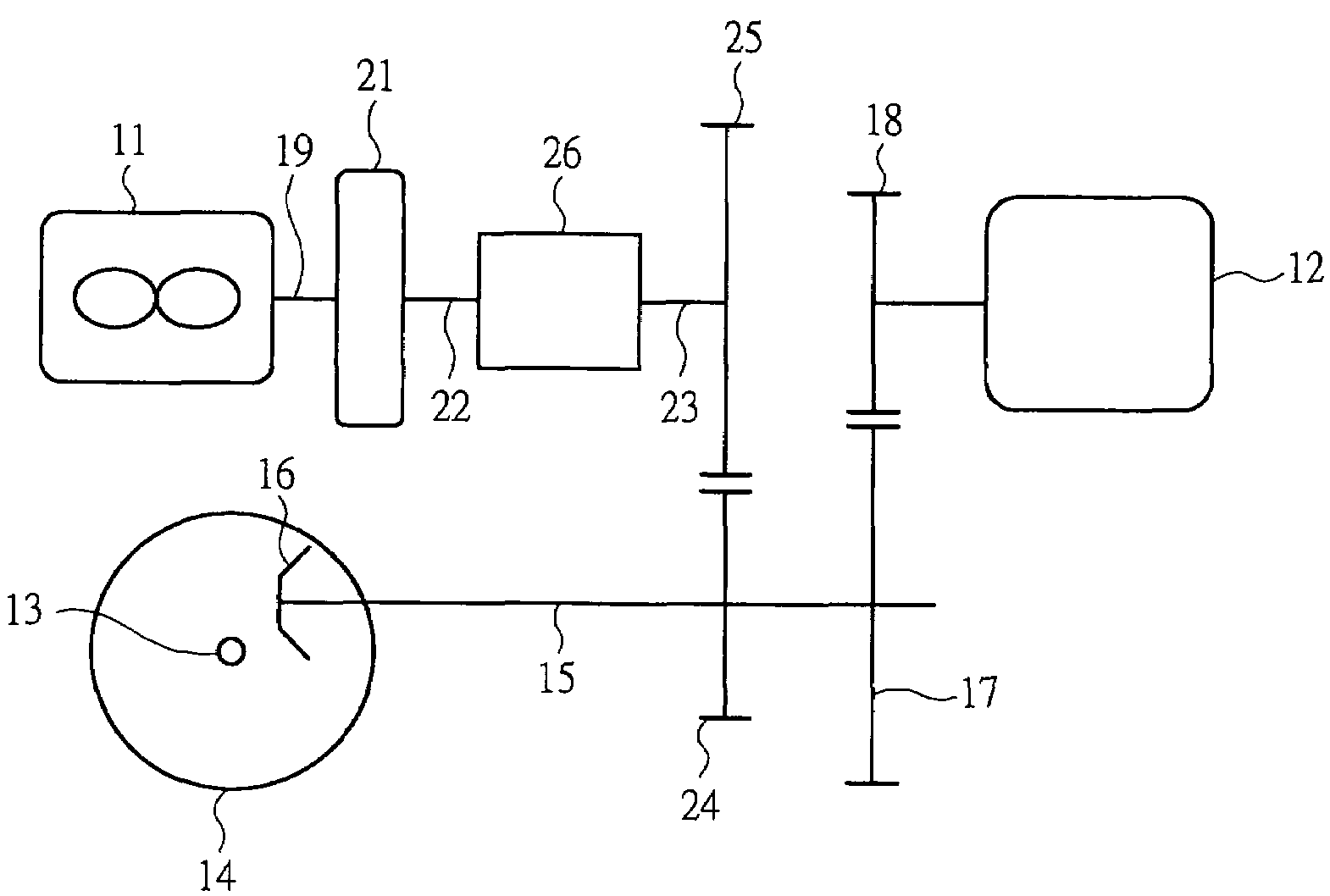
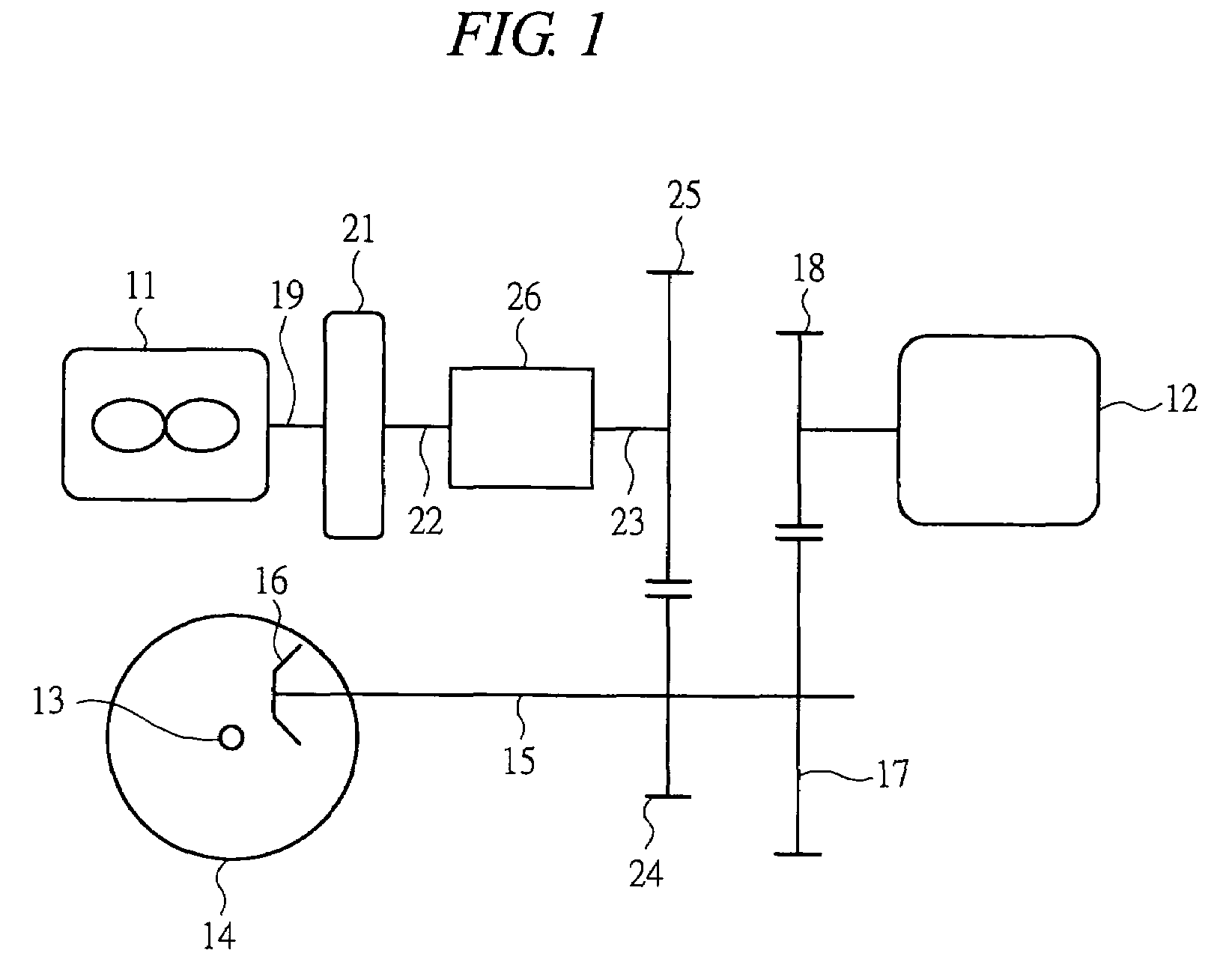
[0044]FIG. 1 is a schematic view showing a power transmission system for a hybrid vehicle. The power transmission system has an engine 11 and a drive motor 12 as a source of power for a vehicle, and is used in a front-wheel drive vehicle. An axle 13 connected to front wheels serving as drive wheels is attached to a differential gear mechanism (not shown), and a final reduction small gear 16 provided on a front-wheel drive shaft 15 is engaged with a final reduction large gear 14 provided in the differential gear mechanism. A drive gear 18 mounted on a main shaft of the drive motor 12 is engaged with a driven gear 17 for speed reduction, which is provided on the front-wheel drive shaft 15, and a motor-power transmission path is formed from the main shaft of the drive motor 12 to the front-wheel drive shaft 15.

[0045]A power generating motor 21 is mounted on a crank shaft 19 of ...


PUM


Abstract

A hybrid vehicle is driven by one or both of an engine and a drive motor. The engine is started by a power generating motor, and power generated by the engine is supplied to a battery. An engine-power transmission path is provided with a coupling for being shifted to a connection state of transmitting engine power to drive wheels and a disconnection state of cutting off the transmission. In connecting the coupling while the drive motor is driven and transmitting engine torque, a revolution speed of the power generating motor is controlled based on that of the drive motor. After a revolution speed of an input-side shaft of the coupling is synchronized with that of an output-side shaft, the coupling is connected. After the coupling is connected, torque of the drive motor and engine is controlled based on required torque of the vehicle.

Description

BACKGROUND OF THE INVENTION[0001]The present invention relates to a control device for a hybrid vehicle that uses an engine and a drive motor together as a source of power.[0002]A hybrid vehicle, which uses an internal combustion engine such as a gasoline engine and an electric motor together as a source of power of the vehicle, includes a series and parallel type. This type of hybrid vehicle is provided with a power generator in addition to the engine and the drive motor, and driving of the vehicle is shifted to any one of driving by the engine, driving by the drive motor, and driving by both of the engine and the motor depending on a running state, whereby the power generator can be driven by the engine at a time of running by the drive motor. The hybrid vehicle can be changed to a motor drive mode of driving the vehicle only by the drive motor, and an engine drive mode of driving the vehicle by the engine or by the drive motor as well as the engine. For example, the vehicle can b...

Claims


Application Information

Patent Timeline
Patent Type & Authority Patents(United States)
IPC IPC(8): B60W10/08B60K1/02B60W20/00B60K6/442B60L50/16B60W10/02B60W10/06F02D29/02
CPCB60K6/387B60K6/48B60K6/485B60W10/02B60W10/06B60W10/08B60W20/00B60K6/38B60K1/02Y10T477/328B60L2240/421B60L2240/423B60L2240/441B60W2510/0638B60W2710/0666B60W2710/081B60W2710/083Y02T10/6221Y02T10/6226Y02T10/6286Y02T10/642Y10T477/26Y10T477/75Y10T477/78Y10T477/30Y10T477/753Y10T477/76Y10T477/79B60K6/442B60W20/10Y02T10/62Y02T10/64B60K2006/268
Inventor NAMBA, ATSUSHI
Owner SUBARU CORP
Why Eureka
Try Eureka