Cold air guide structure of ice-making chamber of cold chamber door

a cold chamber and guide structure technology, applied in the field of refrigerators, can solve the problem of reducing the capacity of the freezing chamber as much

Active Publication Date: 2007-06-12
LG ELECTRONICS INC
View PDF5 Cites 77 Cited by
  • Summary
  • Abstract
  • Description
  • Claims
  • Application Information

AI Technical Summary

Benefits of technology

[0027]An object of the present invention is to provide a guide unit for guiding cold air to allow the cold air to flow to the maximum in an insulated ice-making chamber, which is provided inside of a cold chamber door and in which an ice-making unit is installed.
[0027]An object of the present invention is to provide a guide unit for guiding cold air to allow the cold air to flow to the maximum in an insulated ice-making chamber, which is provided inside of a cold chamber door and in which an ice-making unit is installed.
[0027]An object of the present invention is to provide a guide unit for guiding cold air to allow the cold air to flow to the maximum in an insulated ice-making chamber, which is provided inside of a cold chamber door and in which an ice-making unit is installed.
[0027]An object of the present invention is to provide a guide unit for guiding cold air to allow the cold air to flow to the maximum in an insulated ice-making chamber, which is provided inside of a cold chamber door and in which an ice-making unit is installed.
[0027]An object of the present invention is to provide a guide unit for guiding cold air to allow the cold air to flow to the maximum in an insulated ice-making chamber, which is provided inside of a cold chamber door and in which an ice-making unit is installed.
[0033]To achieve these objects and other advantages and in accordance with the purpose of the invention, as embodied and broadly described herein, there is provided a cold air guide structure of an ice-making chamber of a cold chamber door, the structure including: the cold chamber door; an insulation case disposed inside of the cold chamber door, thermally insulated and having an ice-making chamber therein; an ice-making unit installed in the ice-making chamber of the insulation case, for icing a supplied water by an ice-making cold air and housing pieces of ice; an insulation cover for opening and closing the ice-making chamber of the insulation case; a cold air inlet port for sucking the ice-making cold air into the ice-making chamber; a cold air outlet port for exhausting the ice-making cold air from the ice-making chamber; a cold air supply duct disposed inside wall of the cold chamber, supplied to the cold air through the cold air outlet port; and an ice-making cold air guide unit for guiding the ice-making cold air to a predetermined air passage to suck or exhaust the ice-making cold air into or from the ice-making chamber.

Problems solved by technology

The conventional bottom freezer-type refrigerator has a drawback in that a capacity of the freezing chamber is reduced as much as a space occupied by the ice-making unit installed in the cold chamber.

Method used


Image

  • Cold air guide structure of ice-making chamber of cold chamber door
  • Cold air guide structure of ice-making chamber of cold chamber door
  • Cold air guide structure of ice-making chamber of cold chamber door

Examples


Embodiment Construction

[0053]Reference will now be made in detail to the preferred embodiments of the present invention, examples of which are illustrated in the accompanying drawings. Wherever possible, the same reference numbers will be used throughout the drawings to refer to the same or like parts.

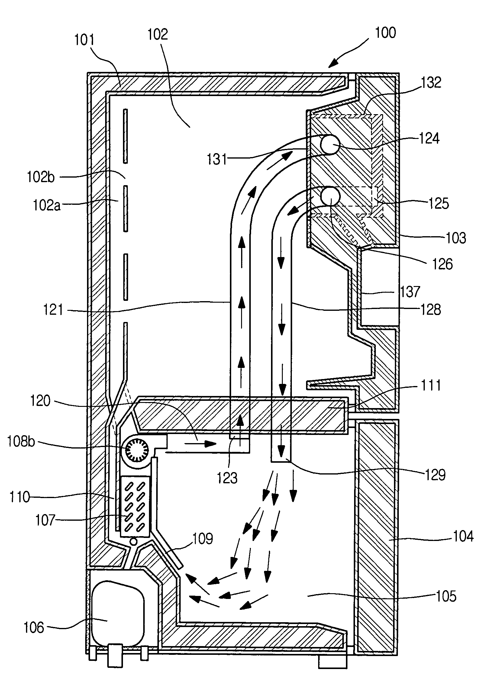
[0054]FIG. 4 is a side sectional view illustrating a bottom freezing chamber-type refrigerator having a cold air guide structure of an ice-making chamber of a cold chamber door according to one embodiment of the present invention.

[0055]As shown in FIG. 4, the bottom freezing chamber-type refrigerator includes a cold chamber 102 and a freezing chamber 105 disposed up and down of a refrigerator body 101; a barrier 111 for partitioning an inner space of the refrigerator into the cold chamber 102 and the freezing chamber 105; doors 1 and 104 rotational connected to the refrigerator body 101 to open and close the cold chamber 102 and the freezing chamber 105; an evaporator 107 and a plurality of ventilation fans ...


PUM


Abstract

The present invention relates to a cold air guide structure of an ice-making chamber of a cold chamber door. The structure including: the cold chamber door; an insulation case disposed inside of the cold chamber door, thermally insulated and having an ice-making chamber therein; an ice-making unit installed in the ice-making chamber of the insulation case, for icing a supplied water by an ice-making cold air and housing pieces of ice; an insulation cover for opening and closing the ice-making chamber of the insulation case; a cold air inlet port for sucking the ice-making cold air into the ice-making chamber; a cold air outlet port for exhausting the ice-making cold air from the ice-making chamber; and an ice-making cold air guide unit for guiding the ice-making cold air to a predetermined air passage to suck or exhaust the ice-making cold air into or from the ice-making chamber.

Description

BACKGROUND OF THE INVENTION[0001]1. Field of the Invention[0002]The present invention relates to a refrigerator, and more particularly, to a cold air guide structure of an ice-making chamber of a cold chamber door in which an ice-making unit is installed in an insulation space (Hereinafter, referred to as “ice-making chamber”) provided inside of the cold chamber door, and cold air can be guided to the maximum into the ice-making chamber.[0003]2. Description of the Related Art[0004]Generally, in a refrigerator, cold air is generated by a refrigeration cycle, which is performed by a compressor, a condenser, an expansive valve and an evaporator, to reduce an internal temperature, thereby freezing a food or keeping the food cool.[0005]The refrigerator is classified into a top mount-type refrigerator having a freezing chamber and a cold chamber partitioned up and down, a bottom freezer-type refrigerator having a cold chamber and a freezing chamber partitioned up and down, and a side by s...

Claims


Application Information

Patent Timeline
Patent Type & Authority Patents(United States)
IPC IPC(8): F25C1/00F25C1/04F25C5/00F25D11/02F25D17/06F25D23/04F25D23/12
CPCF25D17/065F25D23/12F25C1/04F25C5/005F25C2400/10F25D23/04F25D2317/062F25D2317/0664F25D2317/0683F25D2400/04F25D2400/06F25C5/22
Inventor KIM, SEONG JAESEO, CHANG HOLEE, MYUNG RYULCHUNG, SUNG HOON
Owner LG ELECTRONICS INC
Why Eureka
Try Eureka