Tool for removing an object from a workpiece

a technology for removing objects and workpieces, applied in the field of tools, can solve the problems of difficult maintenance, use of free hand drilling, and difficulty in quickly aligning the drill bit with the center of the broken bolt, and achieve the effect of fast and easy removal and quick and easy alignment of the drill bi

Active Publication Date: 2007-06-12
FULGHAM CHARLES A
View PDF10 Cites 29 Cited by
  • Summary
  • Abstract
  • Description
  • Claims
  • Application Information

AI Technical Summary

Benefits of technology

[0008]The present invention is a tool which enables fast and easy removal of an object such as a broken bolt from a workpiece such as an automobile engine block or other engine component. The tool enables a user to quickly and easily align a drill bit over the object to be removed. The tool also enables the user to keep the drill bit aligned with the object during drilling. The tool includes a first arm and a second arm which are pivotably connected together. The pivotable nature of the arms...

Problems solved by technology

However, there are many problems associated with the use of free hand drilling.
Mainly, it is difficult to quickly align the drill bit with the center of the broken bolt.
It is also difficult to ma...

Method used


Image

  • Tool for removing an object from a workpiece
  • Tool for removing an object from a workpiece
  • Tool for removing an object from a workpiece

Examples


Embodiment Construction

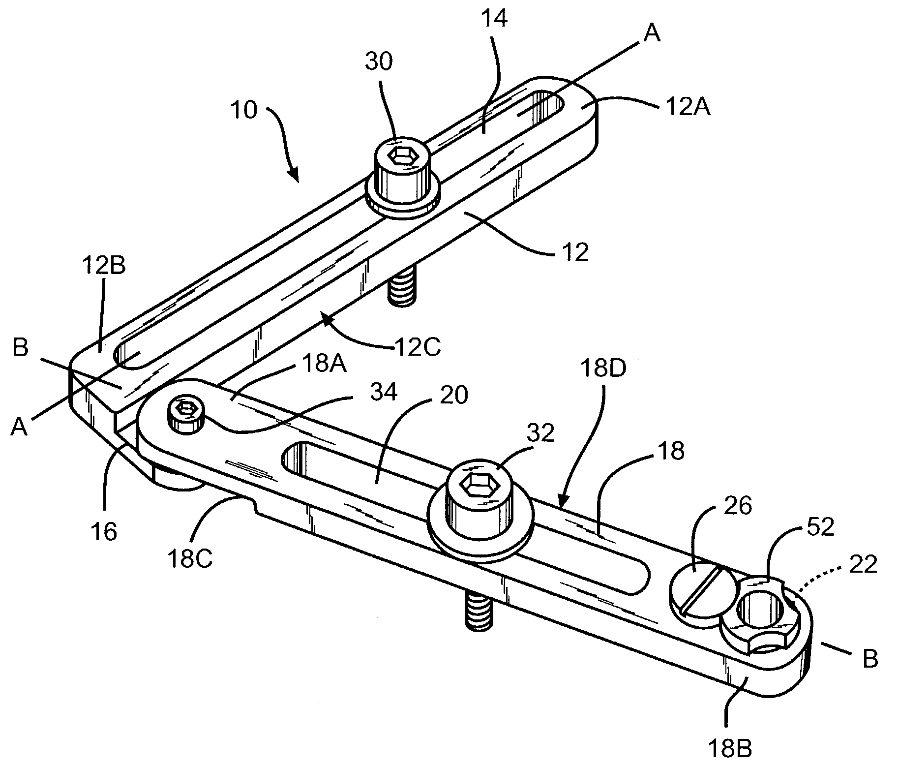
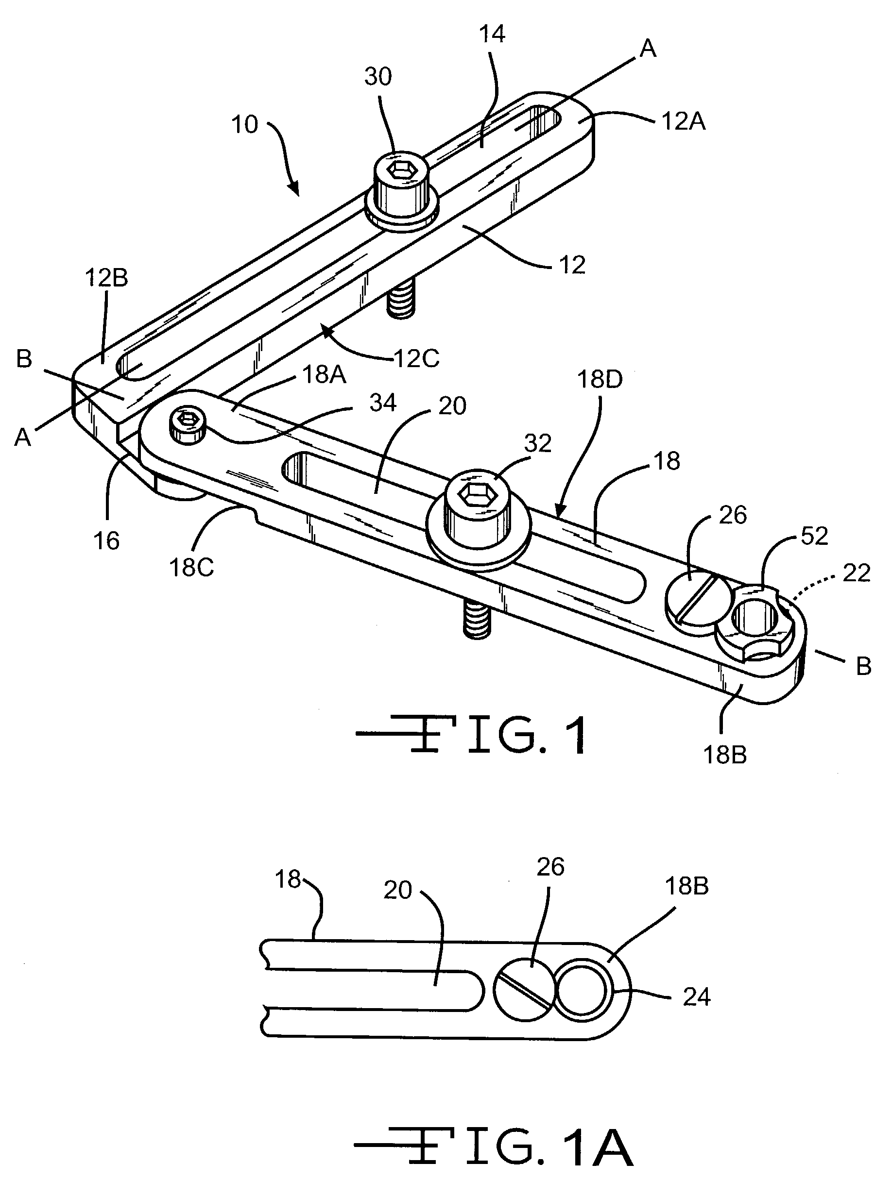
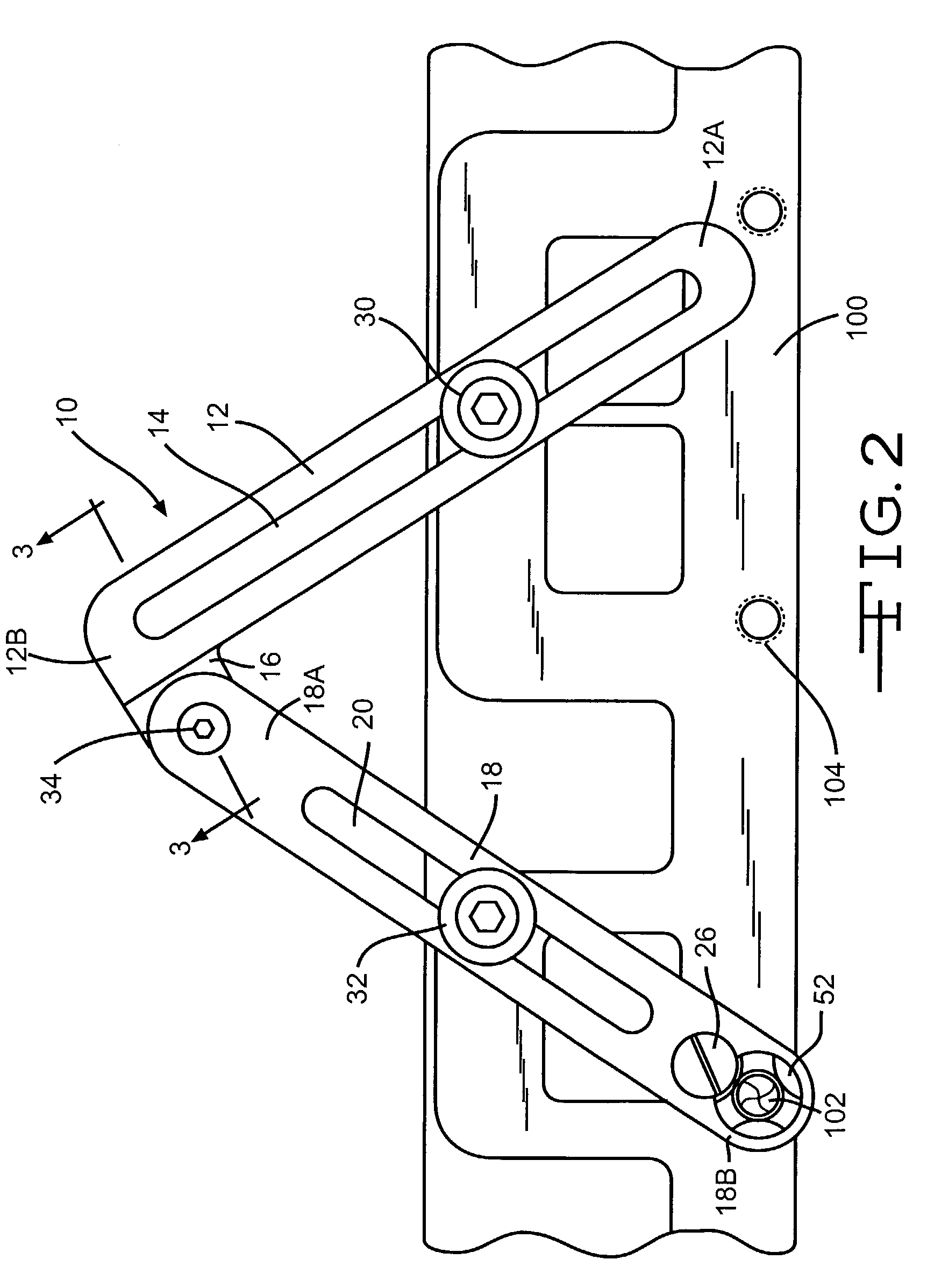
[0021]The tool 10 of the present invention includes a first arm or bracket 12 and a second arm or bracket 18 pivotally connected together. The first arm 12 has opposed first and second ends 12A and 12B forming a longitudinal axis A—A of the first arm 12 (FIG. 1). The first arm 12 has an opening 14 spaced between the ends 12A and 12B. In one (1) embodiment, the opening 14 is a slot which extends between the ends 12A and 12B along the longitudinal axis A—A of the first arm 12. The slot 14 is closed at both ends. The width of the slot 14 depends on the diameter of the securing bolt 30 or 32 used to secure the tool 10 to the workpiece 100. An extension 16 extends outward from the inner side 12C of the first arm 12 at the second end 12B adjacent the bottom side of the first arm 12. In one (1) embodiment, the bottom side of the extension 16 is in the same plane as the bottom side of the first arm 12. The extension 16 has a thickness less than the thickness of the remainder of the first ar...


PUM

PropertyMeasurementUnit
Angleaaaaaaaaaa
Thicknessaaaaaaaaaa
Diameteraaaaaaaaaa

Abstract

A tool for removing an object from a hole in a workpiece which includes a first and second arm pivotably connected together. Each arm having an opening between the ends. The second arm also has a drill hole at the second end. A liner bushing and a drill bushing can be provided in the drill hole. To remove the object from the workpiece, the drill hole is positioned over the object and the arms are adjusted until at least one (1) of the openings of one of the arms is positioned over an existing hole in the workpiece. A securing bolt is then inserted through the opening in the arm into the hole in the workpiece and tightened to secure the tool to the workpiece. Next, a drill bit is positioned in the opening of the drill bushing adjacent the object and rotated until the drill bit is completely through the object.

Description

CROSS-REFERENCE TO RELATED APPLICATION[0001]This application claims the benefit of U.S. Provisional Application Ser. No. 60 / 389,444, filed Jun. 17, 2002.STATEMENT REGARDING FEDERALLY SPONSORED RESEARCH OR DEVELOPMENT[0002]Not ApplicableBACKGROUND OF THE INVENTION[0003](1) Field of the Invention[0004]The present invention relates to a tool which allows for quick and easy removal of objects from a hole in a workpiece. In particular, the tool of the present invention allows for quick and accurate removal of broken bolts from threaded holes in engine components.[0005](2) Related Art[0006]In the past, objects, such as broken bolts, which were stuck in holes in a workpiece were removed from the holes by free hand drilling. However, there are many problems associated with the use of free hand drilling. Mainly, it is difficult to quickly align the drill bit with the center of the broken bolt. It is also difficult to maintain the alignment which results in crooked drilling and damage to the ...

Claims


Application Information

Patent Timeline
IPC IPC(8): B23B47/28
CPCB23B47/284B23B2215/24Y10T408/567Y10T408/569B23B2260/124
Inventor FULGHAM, CHARLES A.
Owner FULGHAM CHARLES A
Why Eureka
Try Eureka