Paddle hand grips and method for making and using same

a technology of hand grips and shafts, applied in the field of hand grips, can solve the problems of hand and wrist contusion, blisters on the inside palms of the first web space, etc., and achieve the effect of comfortable gripping a shaft, preventing blisters on the hands, and convenient installation

Inactive Publication Date: 2007-06-19
SPLAINE DEBORAH KUTNY
View PDF7 Cites 43 Cited by
  • Summary
  • Abstract
  • Description
  • Claims
  • Application Information

AI Technical Summary

Benefits of technology

[0012]It is an object of the invention to provide a hand grip that enables a user to comfortably grip a shaft and to prevent blisters on the hands.
[0013]It is a further object of the invention to provide a handgrip that is easily installed on a shaft.
[0014]It is a further object of the invention to provide indexing on any paddle for either right or left handed people on any round paddle shaft, and to provide proper hand placement for each individual by permitting custom adjustment on the paddle shaft.
[0016]It is a further object of the invention to insure proper hand placement without the hands slipping on the paddle shaft.
[0020]Furthermore, these comfort grips are manufactured with die cut closed cell rubber material in a predetermined thickness. This material will not absorb water to add weight to the grip which would be detrimental to the intended use. Additionally, the closed cell rubber material may be fused on one side with nylon material to add UV (ultraviolet) protection and extended useful life, and may be manufactured with an ingrained texture on the opposite side to add gripping ability, decrease slippage of grip and increase paddling efficiency, provide a soft feel, ease of installation on the paddle and a desired color (including colors for water safety), for the end user.

Problems solved by technology

This motion causes significant friction between the shaft and hands during the paddling motion which causes blistering and calluses on the first web space and skin on the inside palms of the hands.
Furthermore, this grasp on the paddle contributes to contusions (bruising) to the underlying metacarpal bones of the hand and phalanx bones of the fingers.
People with disabilities of the hand and wrist (for example carpal tunnel syndrome, tendon injuries and arthritis) would be unable or too uncomfortable to hold a tight grip on the smooth hard shaft of the paddle.
While paddle shafts having oval cross-sections provide a degree of indexing, such indexing has not been available on paddles having circular shafts.
Without having an index for the tips of the fingers, proper technique cannot be accomplished.
Keeping the paddler's hands from sliding to the left or right during paddling is especially difficult when the paddle is wet.

Method used


Image

  • Paddle hand grips and method for making and using same
  • Paddle hand grips and method for making and using same
  • Paddle hand grips and method for making and using same

Examples


first embodiment

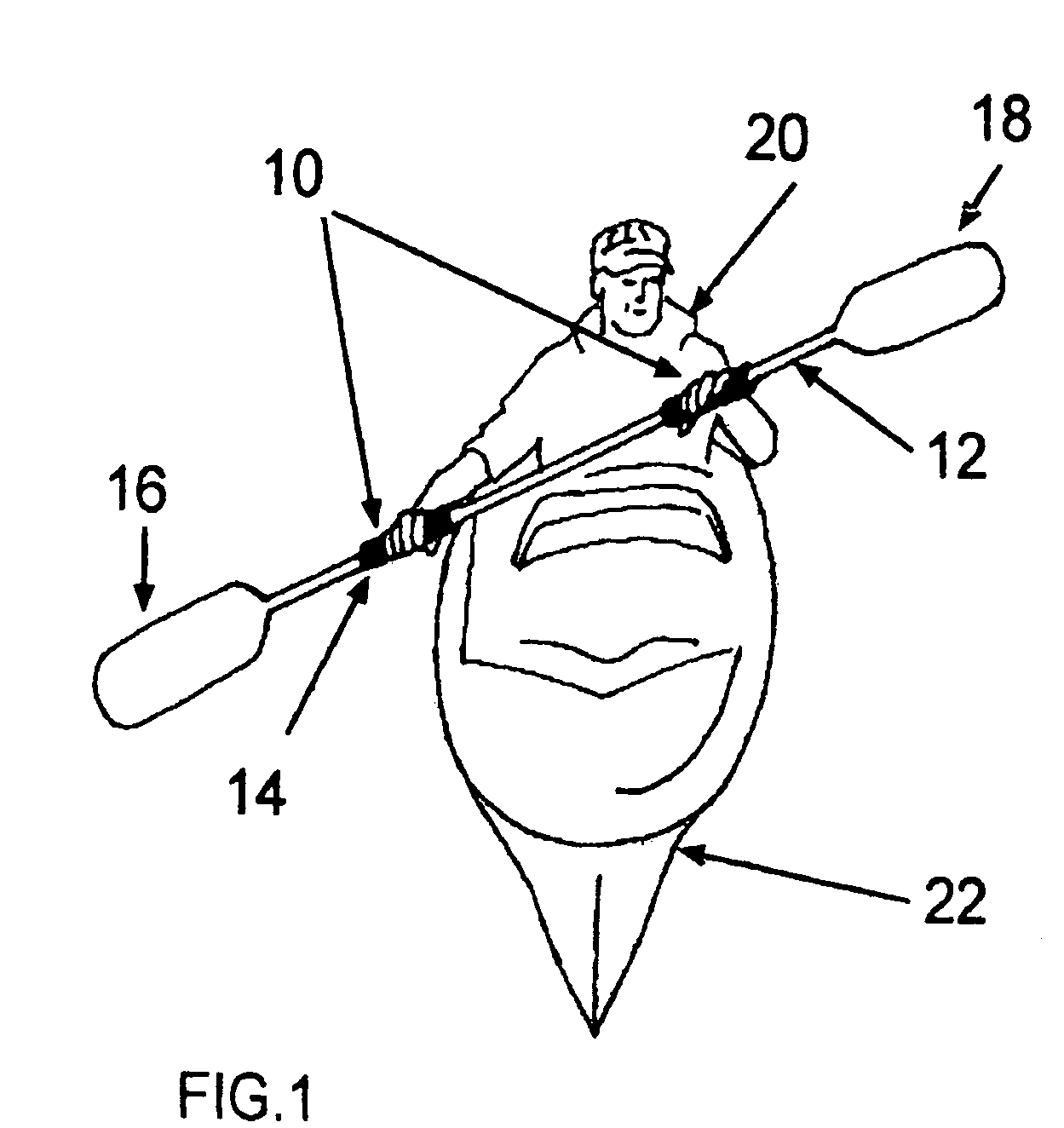
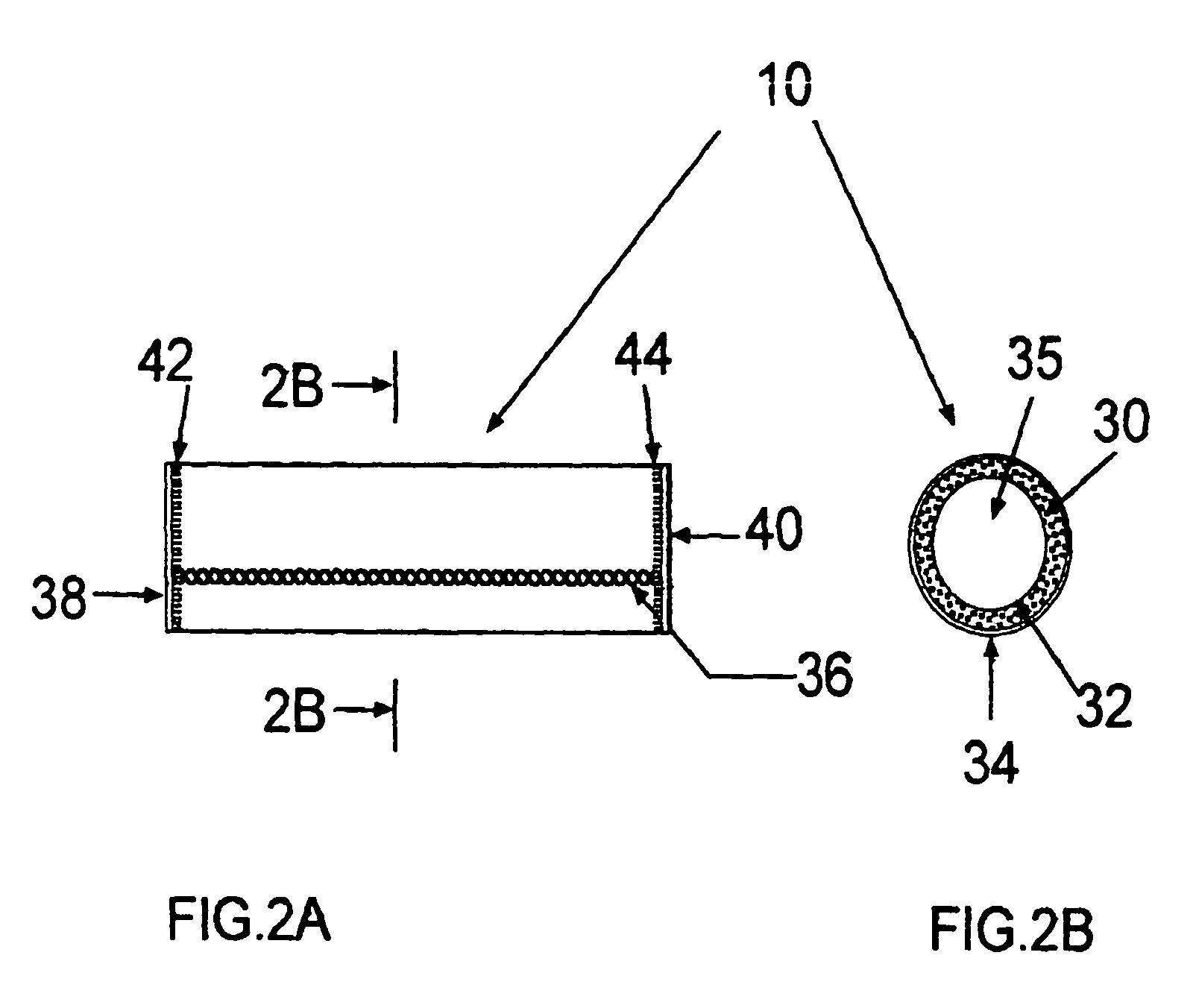
[0050]This first embodiment of the invention illustrated in FIG. 2A and FIG. 2B has particular application to the case where the paddle or oar of FIG. 1 may be disassembled at a central portion along its shaft 12. In the disassembled configuration, water may be applied to the shaft and to the inner surface of the grip 10. The grip may then be forced to slide down the shaft to a desired position.

[0051]Referring to FIG. 3A and FIG. 3B, in this second embodiment of the invention, the tubular structure of the grip 10A is established by the use of a lace 50, threaded through a series of die cut holes 52. This structure is similar to that of the first embodiment, and will thus not be described in detail. However, the use of a lace permits grip 10A to be assembled on to the shaft of an oar or paddle that does not come apart, so that there is no difficulty with respect to the size of the blades preventing insertion of the shaft. The rectangular piece of material from which grip 10A is forme...

third embodiment

[0052]Referring to FIG. 4A and FIG. 4B, in the invention, the tubular structure of grip 10B is formed by using hook and loop fasteners, of a type well known in the art. This embodiment may be used with oars or paddles which have shafts that disassemble and shafts that do not disassemble. The material is stretched to allow the hook and loop fasteners to be closed. There is an overlap of the sides which are connected to form the tubular structure as shown in FIG. 4A.

[0053]Referring to FIG. 5A and FIG. 5B, in another embodiment of the invention, a zipper 70, having a first side 72 attached to a first connecting portion and a second side 74 attached to a second connecting portion of the material of grip 10C, has a zipper closure 76, with a zipper pull 78 extending therefrom. This embodiment may be used with oars or paddles which have shafts that disassemble and shafts that do not disassemble. The material is stretched when the zipper is closed.

[0054]Referring to FIG. 6A and FIG. 6B, in ...


PUM

PropertyMeasurementUnit
thicknessaaaaaaaaaa
lengthaaaaaaaaaa
lengthaaaaaaaaaa

Abstract

A comfort hand grip for a shaft comprises a tubular member formed of a closed cell resilient polymer material core; and a water resistant coating on each side of the core. The comfort grip is sized so as to be slightly stretched when positioned on a shaft, and includes an indexing mark for proper orientation of the paddle. The resilient polymer core may be formed of a rubber, and the coating of an ultraviolet resistant flexible material such as nylon. The hand grip may be formed from a die cut generally rectangular piece of material which is formed into the tubular structure by at least one of, for example, stitching which joins the opposite sides to one another; a lace through openings in joining portions of the material along the sides; a zipper having a side along each of the joining portions; and a set of hook and loop closures on opposite ones of the joining portions.

Description

[0001]This application is a continuation-in-part of application Ser. No. 10 / 658,853 filed on Sep. 10, 2003 now abandoned, which claims priority under 35 U.S.C. §119(e) from provisional patent application Ser. No. 60 / 409,678 filed on Sep. 10, 2002 and provisional patent application Ser. No. 60 / 421,621, filed on Oct. 28, 2002, all of which are incorporated herein by reference, in their entirety.BACKGROUND OF THE INVENTION[0002]1. Field of the Invention[0003]The present invention relates to articles for making gripping of a shaft more comfortable. In particular, it relates to hand grips that serve to make the use of a shaft, such as that of an oar or paddle more comfortable and efficient and assists people with hand and wrist disabilities in paddling. More particularly, it relates to hand or comfort grips which may be applied to the shaft of an oar or paddle and improve the performance of a user's existing paddle (without having to purchase a new or more expensive custom paddle) used w...

Claims


Application Information

Patent Timeline
Patent Type & Authority Patents(United States)
IPC IPC(8): B63H16/04
CPCB63H16/04B63B2221/00B63B2231/50
Inventor SPLAINE, DEBORAH KUTNY
Owner SPLAINE DEBORAH KUTNY
Why Eureka
Try Eureka