Intervertebral implant

a technology of intervertebral implants and implants, which is applied in the field of intervertebral implants, can solve the problems of entail pseudoarthrosis and lack of rigid connection of horseshoe shaped intervertebral implants, and achieve the effects of reducing the danger of plastic cracking, radial elongation, and high clamping forces

Inactive Publication Date: 2007-06-19
DEPUY SYNTHES PROD INC
View PDF186 Cites 428 Cited by
  • Summary
  • Abstract
  • Description
  • Claims
  • Application Information

AI Technical Summary

Benefits of technology

[0009]As regards a second embodiment mode, a front plate is mounted at the front surface of the three dimensional (3D) implant structure so as to be configured vertically to the horizontal center plane of the intervertebral implant, said boreholes passing through said front plate and receiving the anchored longitudinal affixation elements. Compared to the state of the art of a two-part implant, wherein a front plate is implanted in a separate operational step, the above design of the present invention offers the advantage that the intervertebral implant shall be implanted in a single step and hence in a simple and quicker manner. The invention offers a further advantage in that the intervertebral implant shall be affixed as frontally to the vertebra as possible, namely at a place where good bone material may be expected to be. As a result anterior displacement is restricted without thereby incurring greater danger to the surrounding structures than when using a state of the art intervertebral implant. The load still is being borne by the compressed vertebral implant, not by the front plate or the affixation screws.
[0027]The borehole may be in the form of a metal bush fitted with an inner thread for the purpose of improving anchoring the bone screw in the plastic implant structure. The intervertebral implant also may consist partly of plastic and, in the borehole zones, of metal. This design offers improved guidance and anchoring of the bone screw in the intervertebral implant.

Problems solved by technology

This design incurs the drawback that the inserted affixation screws may be anchored into the bone only by their shanks, a rigid connection with the horseshoe shaped intervertebral implant being lacking.
As soon as the anchoring of the bone screw in the bone is weakened, the intervertebral implant becomes displaceable relative to the screw and the bone screws may then migrate while endangering the blood vessels.
Moreover the loosening of the intervertebral implant may entail pseudoarthrosis.

Method used


Image

  • Intervertebral implant
  • Intervertebral implant
  • Intervertebral implant

Examples


Embodiment Construction

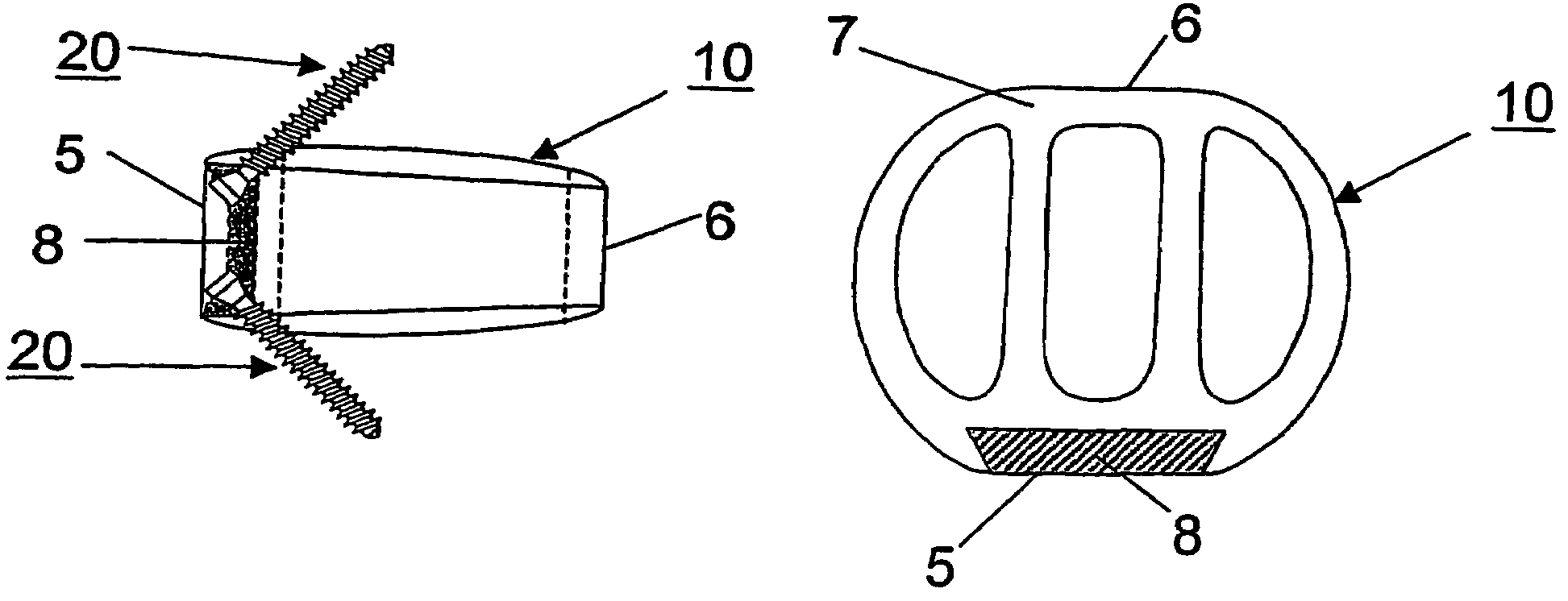
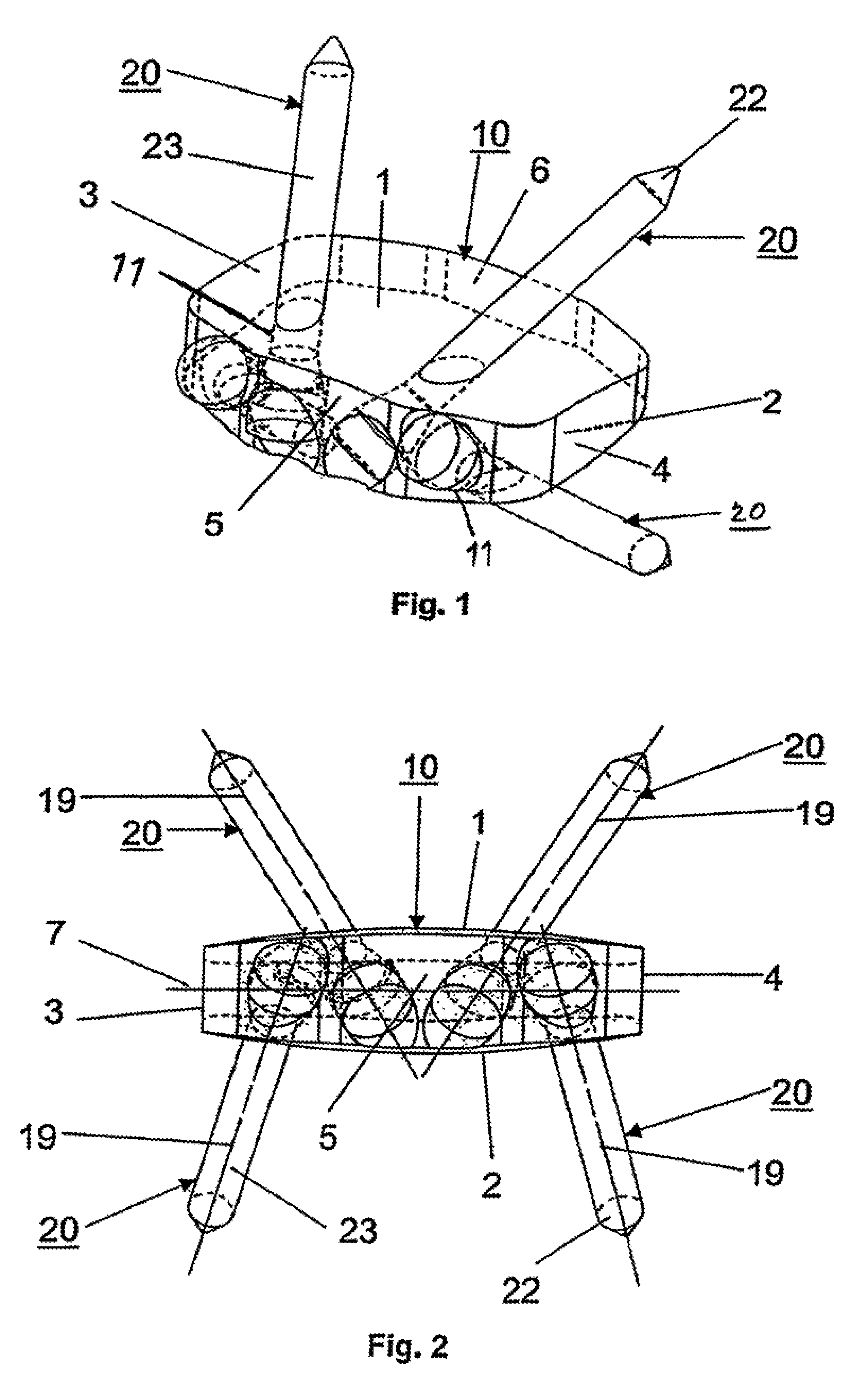
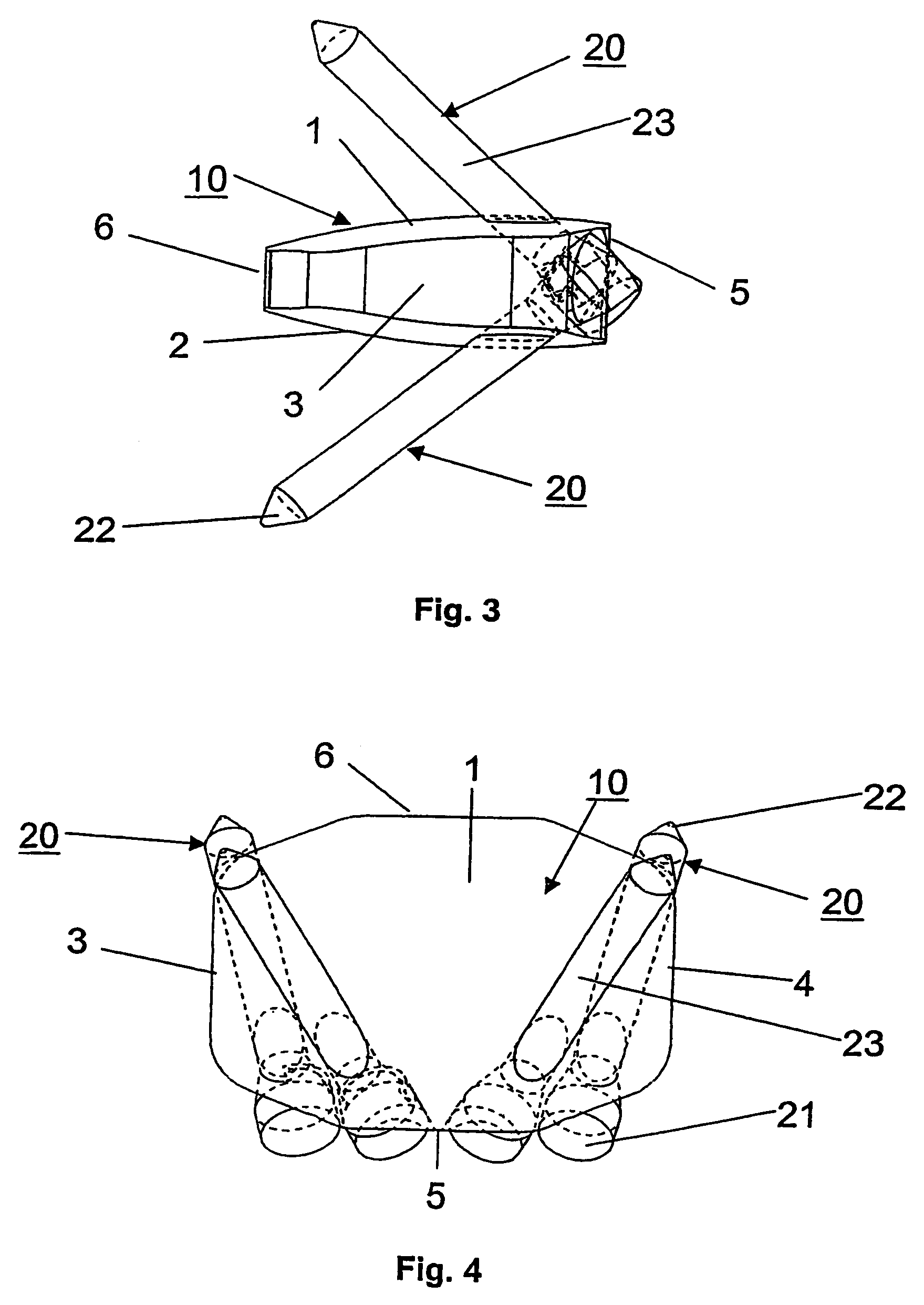
[0037]The intervertebral implant of FIGS. 1 through 4 consists of a 3D structure 10 exhibiting both a convex top side 1 and a convex underside 2, the two sides each being designed to rest against the end plates of two adjacent vertebras. To attain improved anchoring, the top side 1 and the underside 2 may be topographically shaped and be fitted with grooves, ribs or teeth, or their surfaces may be merely roughened.

[0038]The 3D implant structure 10 moreover comprises a left side face 3 and a right side face 4, also a front face 5 and a rear face 6. The implant structure 10 also may be hollow and its outer surface may comprise perforations.

[0039]The implant structure 10 comprises a plurality of boreholes 9 passing through it and receiving longitudinal affixation elements 20. Preferably four such boreholes 9 shall be provided.

[0040]At least one of the boreholes 9 is designed in a way that the longitudinal affixation element 20 received therein may be rigidly connected to the interverte...


PUM


Abstract

The intervertebral implant is in the form of a three-dimensional structure (10) comprising (a) a top side (1) and an underside (2) which are designed to rest against the end plates of two adjacent vertebras, (b) a left side face (3) and a right side face (4), (c) a front face (5) and a rear face (6), (d) a horizontal center plane situated between the top side (1) and the underside (2), (e) a vertical center plane (8) situated between the left side face (3) and the right side face (8) and (f) a plurality of boreholes (9) passing through the implant structure (10) that are designed to receive longitudinal affixation elements (20), the axes (19) of said elements intersecting the horizontal center plane (7). At least one of the boreholes (9) is designed in a manner that the affixation element (10) received in it can be rigidly connected to the intervertebral implant. Said connection is implemented using a thread or by matching conical surfaces.

Description

CROSS-REFERENCE TO RELATED APPLICATIONS[0001]This is a continuation of International Application No. PCT / CH02 / 00099, filed Feb. 19, 2002, the entirety of which is expressly incorporated by reference herein.FIELD OF THE INVENTION[0002]The present invention relates to an intervertebral implant.BACKGROUND OF THE INVENTION[0003]Such an intervertebral implant is known from the British patent document 2,207,607 A which discloses a horseshoe implant structure having a plurality of cylindrical holes. These holes are fitted with inner, smooth surfaces and comprise only one stop for the heads of the bone screws to be inserted into them. This design incurs the drawback that the inserted affixation screws may be anchored into the bone only by their shanks, a rigid connection with the horseshoe shaped intervertebral implant being lacking. As soon as the anchoring of the bone screw in the bone is weakened, the intervertebral implant becomes displaceable relative to the screw and the bone screws m...

Claims


Application Information

Patent Timeline
Patent Type & Authority Patents(United States)
IPC IPC(8): A61F2/44A61B17/80A61B17/86A61F2/00A61F2/30
CPCA61B17/8052A61F2/442A61F2/4465A61B17/86A61F2002/30004A61F2310/00011A61F2002/30777A61F2002/30794A61F2002/30841A61F2002/4475A61F2250/0014A61F2002/30774A61F2002/3079A61F2002/30593A61F2/44A61F2/4455A61F2/447
Inventor MATHIEU, CLAUDECAIN, CHRISTOPHER MARDEN JOHN
Owner DEPUY SYNTHES PROD INC
Why Eureka
Try Eureka