Well packer having an energized sealing element and associated method

a sealing element and well packer technology, applied in the field of well packers, can solve the problems affecting the sealing effect, and affecting the sealing effect, and achieving the effect of reducing contact force and avoiding failure of seals

Inactive Publication Date: 2007-06-26
SCHLUMBERGER TECH CORP
View PDF36 Cites 90 Cited by
  • Summary
  • Abstract
  • Description
  • Claims
  • Application Information

AI Technical Summary

Benefits of technology

[0010]The present invention provides for an energized sealing element that maintains a seal under various conditions by providing a source of stored energy that can be used to insure contact forces are maintained.

Problems solved by technology

Existing seal elements sometimes fail due to differences in thermal expansion properties of the deformable element and the surrounding casing or formation.
That can lead to a decrease in contact force and a leak may result.
Another failure mode common in open hole completions involves a long sleeve of rubber that is inflated to produce the necessary contact force to form a seal against the surrounding formation.
If pressure is not maintained on the inner wall of the sleeve, the seal is likely to fail.

Method used


Image

  • Well packer having an energized sealing element and associated method
  • Well packer having an energized sealing element and associated method
  • Well packer having an energized sealing element and associated method

Examples


Embodiment Construction

[0020]In the following description, numerous details are set forth to provide an understanding of the present invention. However, it will be understood by those skilled in the art that the present invention may be practiced without these details and that numerous variations or modifications from the described embodiments may be possible.

[0021]The present invention comprises numerous embodiments and associated methods for creating an energized seal as further described below. The seal element of the present invention is for use in downhole packer applications and may be employed on a variety of packers. For example, the seal element may be used on an open hole-type packer, or it may be used on a packer for use inside a casing, liner, or tubing. In addition, the seal element may be employed on an expandable tubing packer.

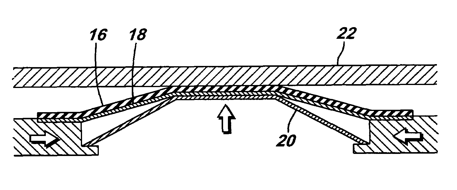
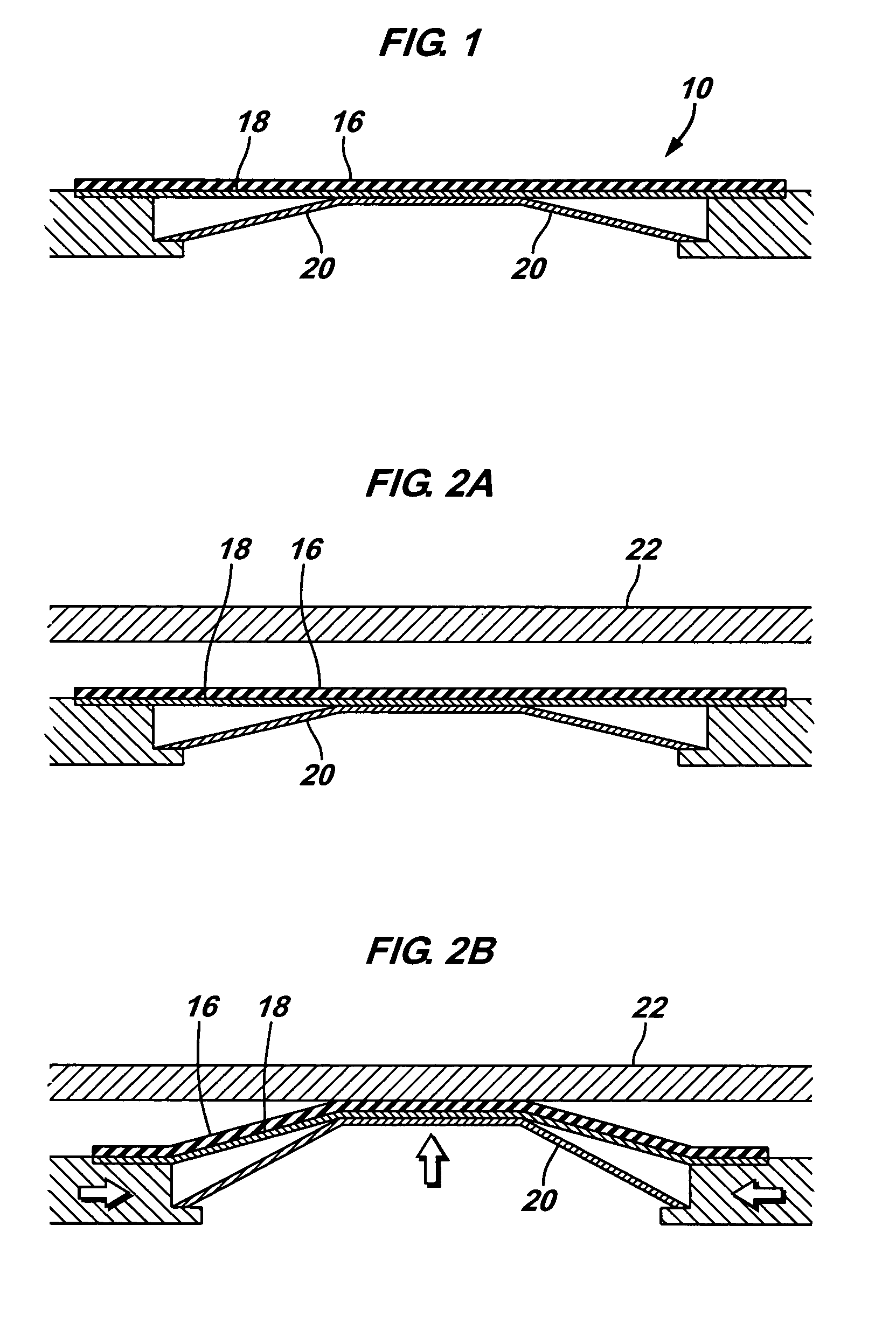
[0022]In the embodiment of FIG. 1, an energized seal element 10 comprises a seal layer 16, a support sleeve 18, and an energizing element 20. Seal layer 16 is prefera...


PUM


Abstract

The present invention provides for a seal assembly that maintains a seal under various conditions by providing a source of stored energy that can be used to insure contact forces are maintained.

Description

[0001]This application claims the benefit of U.S. Provisional Patent Application No. 60 / 508,721, filed on Oct. 3, 2003.BACKGROUND OF THE INVENTION[0002]1. Field of Invention[0003]The present invention relates to the field of well packers, and particularly to a device and method for energizing a well packer seal element.[0004]2. Related Art[0005]Packers are used in oil and gas wells to prevent fluid flow through an annulus formed by a tubing within the well and the wall of the wellbore or casing. The packer is generally integrally connected to the tubing, using, for example, means such as a threaded connection, a ratch-latch assembly, or a J-latch, all of which are well known in the art. The tubing / packer connection generally establishes the seal for the inner radius of the annulus.[0006]The seal for the outer radius of the annulus is generally established by a deformable element such as rubber or an elastomer. A compressive force is generally applied to the deformable element, causi...

Claims


Application Information

Patent Timeline
Patent Type & Authority Patents(United States)
IPC IPC(8): E21B33/12E21B33/127
CPCE21B33/1277E21B33/1208
Inventor GAMBIER, PHILIPPE
Owner SCHLUMBERGER TECH CORP
Why Eureka
Try Eureka