Monolithic integration of cylindrical solar cells

Inactive Publication Date: 2007-06-26
SOLYNDRA RESIDUAL TRUST
View PDF39 Cites 343 Cited by
  • Summary
  • Abstract
  • Description
  • Claims
  • Application Information

AI Technical Summary

Benefits of technology

[0013]In some embodiments, the plurality of photovoltaic cells comprise (i) a first terminal photovoltaic cell at the first end of the substrate, (ii) a second terminal photovoltaic cell at the second end of said substrate, and (iii) at least one intermediate photovoltaic cell between the first terminal photovoltaic cell and the second photovoltaic cell. The transparent conductive layer of each intermediate photovoltaic cell in the at least one intermediate photovoltaic cell is in serial electrical communication with the

Problems solved by technology

However, even when a TCO layer is present, a bus bar network 114 is typically needed in conventional solar cells to draw off current since the TCO has too much resistance to efficiently perform this function in larger solar cells.
Although such cells are highly efficient when they are smaller, larg

Method used


Image

  • Monolithic integration of cylindrical solar cells
  • Monolithic integration of cylindrical solar cells
  • Monolithic integration of cylindrical solar cells

Examples


Embodiment Construction

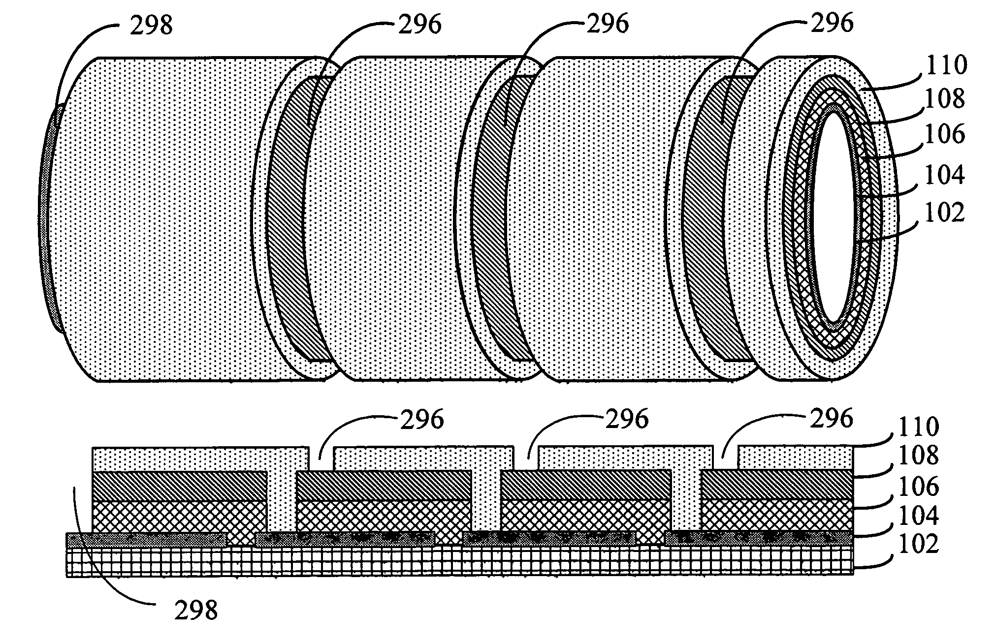
[0041]Disclosed herein are solar cell units comprising a plurality of photovoltaic cells linearly arranged on a substrate in a monolithically integrated manner.

5.1 Basic Structure

[0042]FIG. 7 illustrates the cross-sectional view of an exemplary embodiment of a photovoltaic cell 700. In some embodiments, a solar cell unit comprises a plurality of photovoltaic cells 700 linearly arranged on substrate in a monolithically integrated manner. In some embodiments, the substrate is either (i) tubular shaped or (ii) a rigid solid rod shaped. In some embodiments the substrate is flexible tubular shaped.

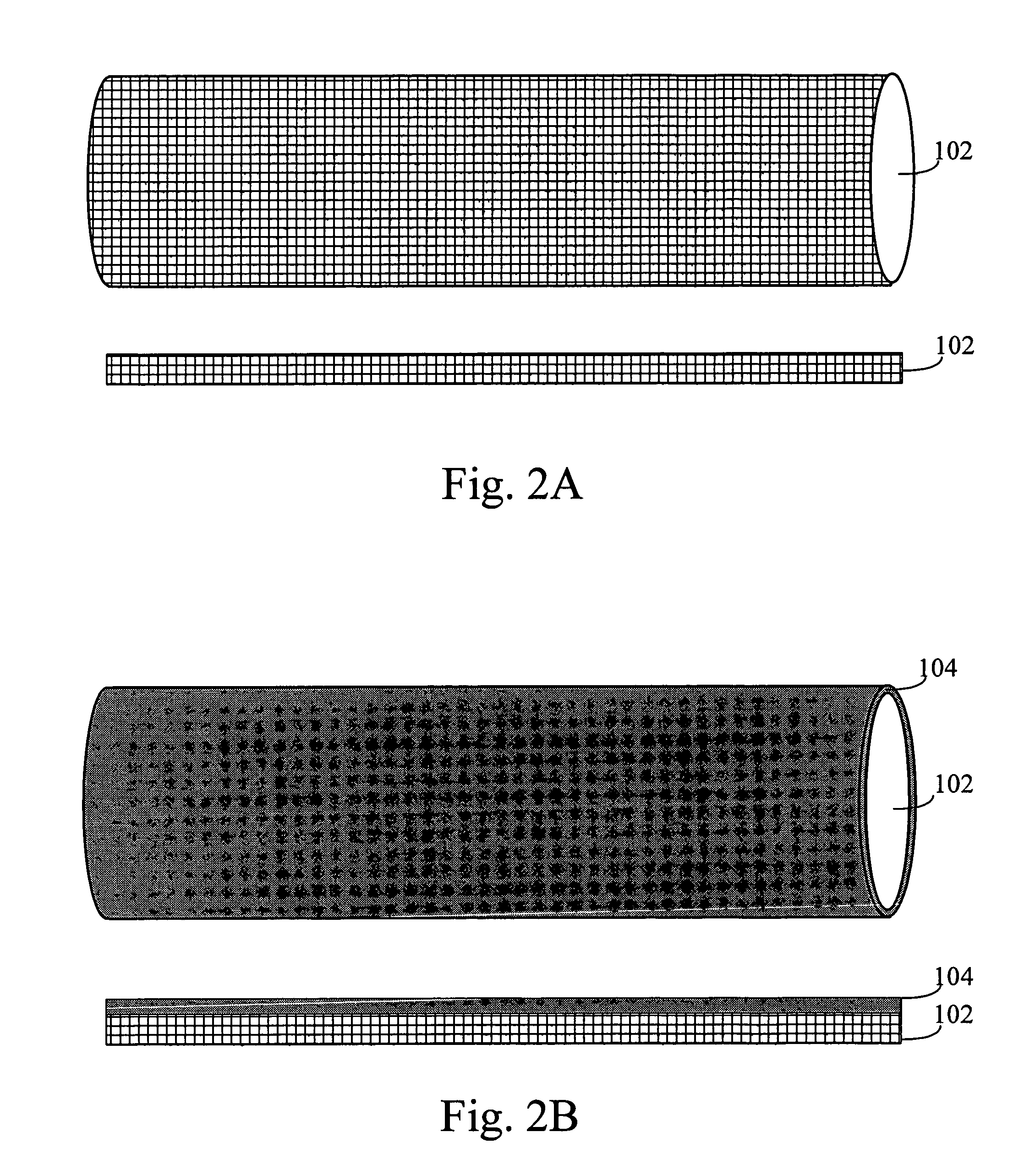
[0043]Substrate 102. A substrate 102 serves as a substrate for the solar cell unit. In some embodiments, substrate 102 is either (i) tubular shaped or (ii) a rigid solid rod shaped. In some embodiments substrate 102 is any solid cylindrical shape or hollowed cylindrical shape. When substrate 102 is tubular shaped it can be either rigid or flexible. For example, in some embodiments substrate 102...


PUM


Abstract

A solar cell unit comprising a substrate and a plurality of photovoltaic cells is provided. The substrate has a first end and a second end. The plurality of photovoltaic cells, which are linearly arranged on the substrate, comprises a first photovoltaic cell and a second photovoltaic cell. Each photovoltaic cell in the plurality of photovoltaic cells comprises (i) a back-electrode circumferentially disposed on the substrate, (ii) a semiconductor junction layer circumferentially disposed on the back-electrode, and, (iii) a transparent conductive layer circumferentially disposed on the semiconductor junction. The transparent conductive layer of the first photovoltaic cell in the plurality of photovoltaic cells is in serial electrical communication with the back-electrode of the second photovoltaic cell in the plurality of photovoltaic cells.

Description

1. FIELD OF THE INVENTION[0001]This invention relates to solar cell assemblies for converting solar energy into electrical energy and more particularly to improved solar cell assemblies.2. BACKGROUND OF THE INVENTION[0002]Solar cells are typically fabricated as separate physical entities with light gathering surface areas on the order of 4-6 cm2 or larger. For this reason, it is standard practice for power generating applications to mount the cells in a flat array on a supporting substrate or panel so that their light gathering surfaces provide an approximation of a single large light gathering surface. Also, since each cell itself generates only a small amount of power, the required voltage and / or current is realized by interconnecting the cells of the array in a series and / or parallel matrix.[0003]A conventional prior art solar cell structure is shown in FIG. 1. Because of the large range in the thickness of the different layers, they are depicted schematically. Moreover, FIG. 1 i...

Claims


Application Information

Patent Timeline
IPC IPC(8): H01L31/05
CPCH01L31/035281H01L31/055H01L31/046H01L31/0475Y02E10/52Y02E10/60H01L31/054H02S40/44H01L31/0463Y02E10/541Y02E10/543Y02P70/50H01L27/142
Inventor BULLER, BENYAMINBECK, MARKUS E.
Owner SOLYNDRA RESIDUAL TRUST
Why Eureka
Try Eureka