Digital broadband frequency measurement

a technology of digital broadband and frequency measurement, applied in the field of digital broadband frequency measurement, can solve the problems of increasing the size and weight of the device, the size of the cable may be limited, and the size of the receiver, so as to eliminate delay and gain uncertainties, and be ready to purchase

Active Publication Date: 2007-06-26
BAE SYST INFORMATION & ELECTRONICS SYST INTERGRATION INC
View PDF25 Cites 6 Cited by
  • Summary
  • Abstract
  • Description
  • Claims
  • Application Information

AI Technical Summary

Benefits of technology

[0009]The present invention addresses some of the shortcomings of the prior art by providing an improved IFM receiver that replaces analog delay lines with digital delay lines that incorporate a field programmable gate array (FPGA), an application specific integrated circuit (ASIC) or other digital processor. The cost associated with the production of the IFM of the present device is significantly cut because components can be readily purchased without customized modifications. The processing associated with the present invention can be accomplished through the use of a standard FPGA and calibration is eliminated due to the elimination of delay and gain uncertainties associated with the analog delay line.

Problems solved by technology

Although IFM receiver technology is well known and fairly effective, the major disadvantage of the prior art relates to the size, weight and costs associated with the production of the receivers.
The IFM receivers used in the prior art usually require analog delay lines that can be up to ten to twenty feet long and therefore increase the size and weight associated with the devices.
The size of cable may be limited because it cannot be infinitesimally small since it needs to operate at several GHz frequencies with reasonably small losses.
The IFM receivers are typically custom designed and built in small quantities and, therefore, require a significant amount of labor and calibration associated with them.

Method used


Image

  • Digital broadband frequency measurement
  • Digital broadband frequency measurement

Examples


Embodiment Construction

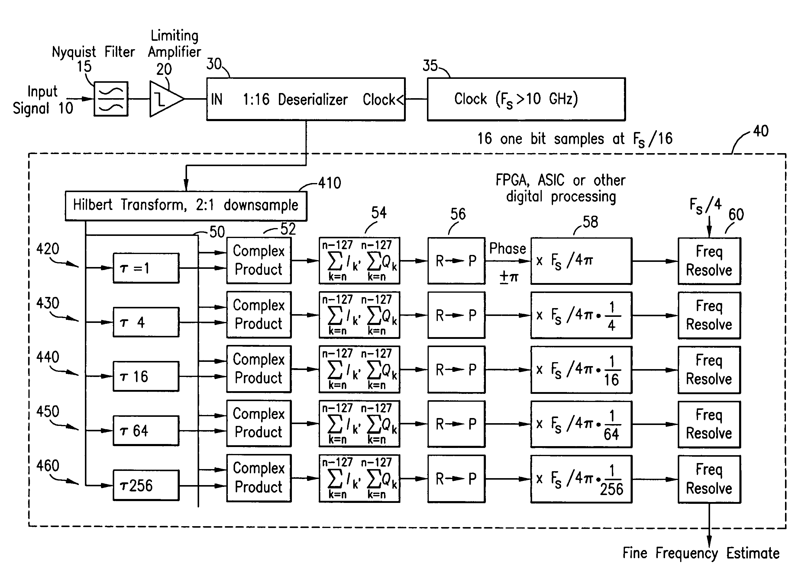
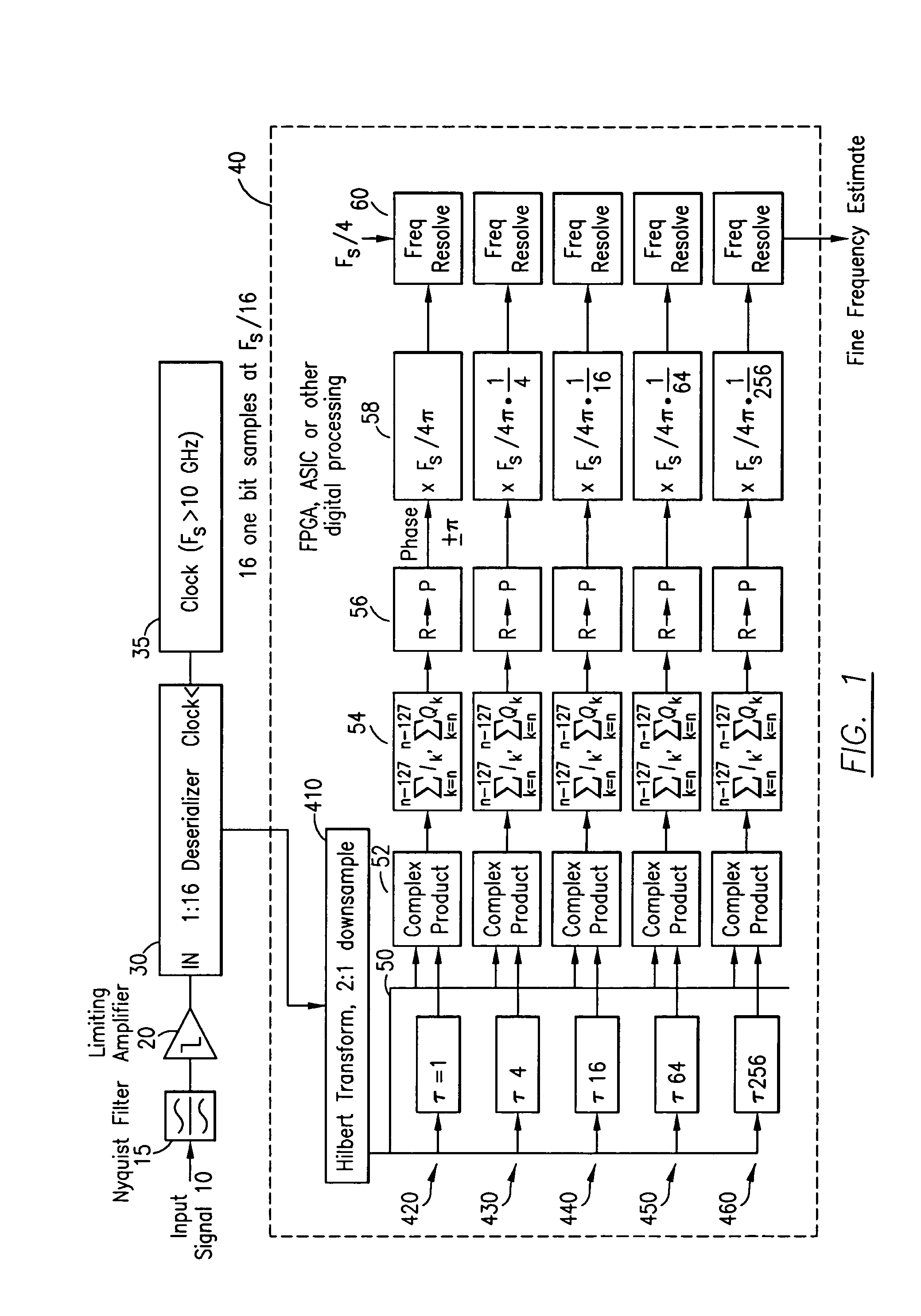
[0014]The present invention relates to a device and method that digitally replicates the analog processing that is normally associated with an IFM. Digital components exist today which operate at frequencies from 10 GHz to 40 GHz. The present invention advantageously quantizes a RF signal by using a limiting amplifier and then samples through a high-speed digital circuit a 1 bit data stream that contains all of the information necessary to resolve the frequency of input signals to the same accuracy as an analog IFM. The processing of the one bit data stream may be accomplished by demultiplexing the data into parallel words that may result in a data rate that could be handled by the existing state of the art FPGA or ASIC. The processing algorithm only needs to replicate digitally the analog processing of a traditional

[0015]FIG. 1 shows the digital frequency measurement system according to the present invention. Filter 15 receives an input signal 10 for frequency band selection. The f...


PUM


Abstract

The present invention relates to a device and method that digitally replicates the analog processing that is normally associated with an instantaneous frequency measurement device. Specifically, the present relates to a digital frequency measurement device comprising: a filter, where the filter receives an input RF signal and transmits an output signal centered around a desired frequency; a limiting amplifier downstream of the filter, where the amplifier receives and amplifies the output signal; a deserializer downstream of the amplifier that continuously samples the output signal from the limiting amplifier; and a digital frequency measurement processor (DFM), where the DFM receives data at a rate of 1 / 16 of the deserializer sample rate. The DFM transforms the data into multiples stages that are combined in order to produce an estimate of the input signal, where the DFM is implemented through a digital processing device.

Description

BACKGROUND OF THE INVENTION[0001]1. Field of the Invention[0002]The present invention relates to a system and method for digital broadband frequency measurement.[0003]2. Description of Related Art[0004]The conventional instantaneous frequency measurement (IFM) receiver is a radio frequency (RF) receiver used primarily in electronic warfare. The IFM measures the frequency of pole signals radiated from a hostile radar and measures the frequencies of incoming RF signals utilizing interferometric techniques by detecting the phase shift magnitudes produced in multiple calibrated delay lines. During normal operation, the received RF signal may be divided and simultaneously introduced into a non-delayed path and a delayed line of known length. The phase differences between the delayed and non-delayed receiver paths are functions of the input signal frequency that include the conversion of the phase different signals and provide signals whose amplitudes are related to the phase delay. The s...

Claims


Application Information

Patent Timeline
Patent Type & Authority Patents(United States)
IPC IPC(8): G01R23/00H04K1/02G01R13/02G01R23/165
CPCG01R23/165
Inventor HUGGETT, JAMES M.
Owner BAE SYST INFORMATION & ELECTRONICS SYST INTERGRATION INC
Why Eureka
Try Eureka