Casting mold

a mold and casting technology, applied in the field of casting molds, can solve the problems of time-consuming and labor-intensive processes for producing castings with holes introduced at a later stage, in particular through holes, and achieve the effect of producing components with holes

Inactive Publication Date: 2007-07-03
SIEMENS AG
View PDF18 Cites 29 Cited by
  • Summary
  • Abstract
  • Description
  • Claims
  • Application Information

AI Technical Summary

Benefits of technology

[0006]Consequently, it is an object of the invention to provide a casting mold which allows the production of a component with holes, in particular with through-holes, more easily and more quickly.

Problems solved by technology

The laser beam guidance is very complex.
Consequently, processes for producing a casting with holes which are introduced at a later stage, in particular through-holes, are therefore time-consuming.

Method used


Image

  • Casting mold
  • Casting mold
  • Casting mold

Examples


Embodiment Construction

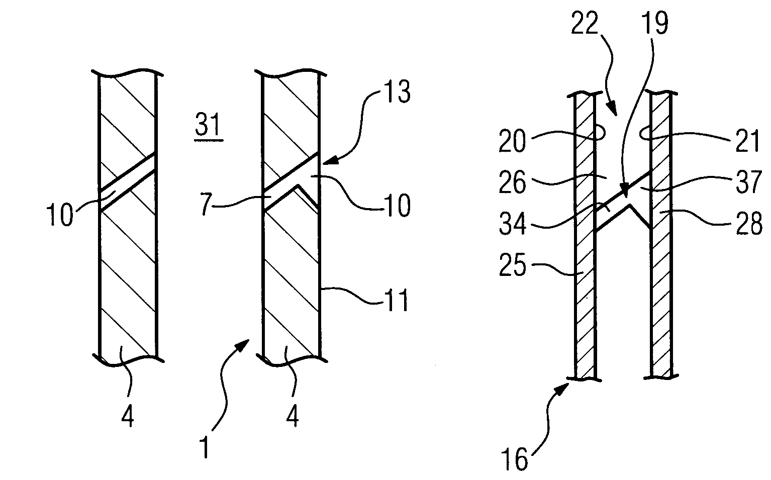
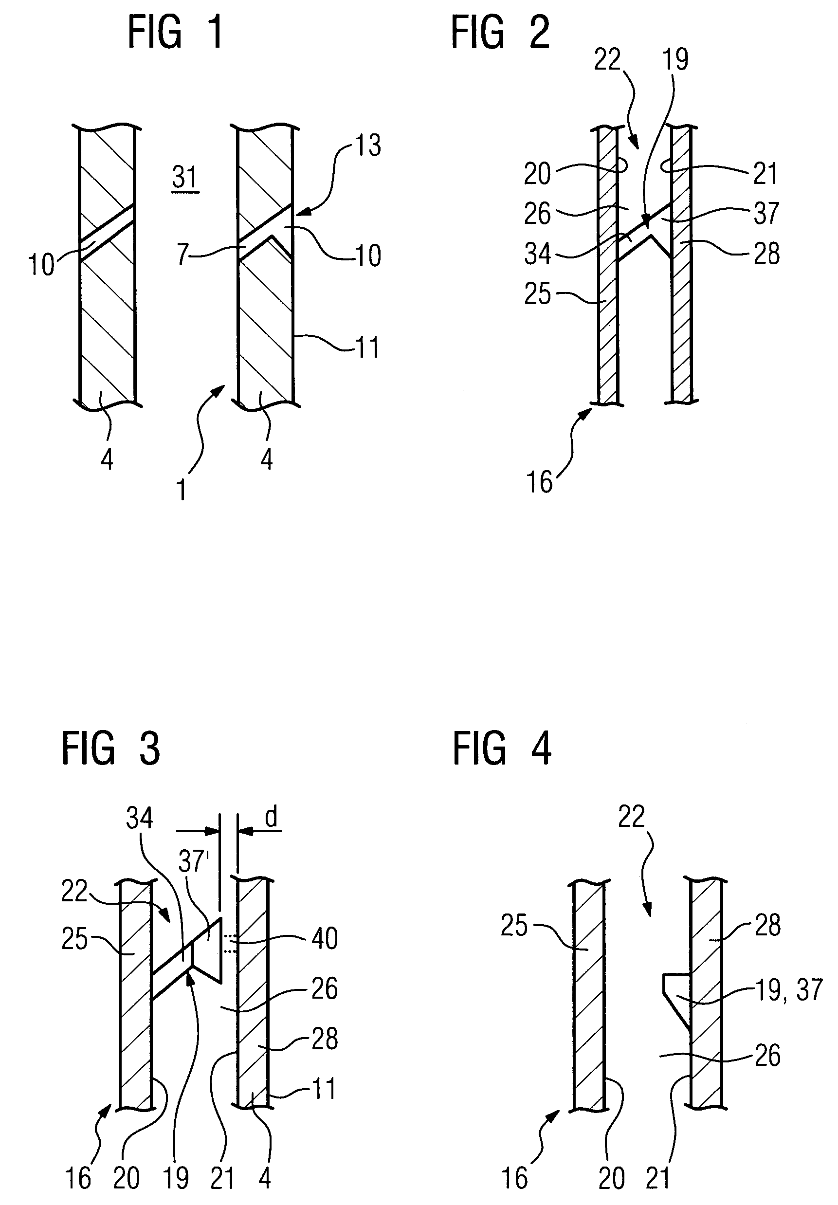
[0017]FIG. 1 shows a component 1 which, by way of example, at least in part has a cavity 31 and can be produced using the casting mold according to the invention. Therefore, the component 1 has a wall 4, in particular an outer wall 4. At least one hole 13, in this case a through-hole 13, is formed in the wall 4. The component 1 may, for example, be metallic or ceramic. By way of example, it is a turbine component 1 of a gas turbine 100 (FIG. 7) or steam turbine 300, 303 (FIG. 9). This component is, for example, a turbine blade or vane 120, 130, 354, 357 (FIG. 7) or a combustion chamber lining 155 (FIG. 8), which consists, for example, of an iron-, nickel- or cobalt-base super alloy. In components 1 of this type, through-holes 13 are used, for example, to cool the component 1 by film cooling. The through-hole 13 consists, for example, of a round or oval hole part 7 which widens out from the cavity 31 to the outer surface 11 of the wall 4 to form a diffuser 10. Components 1 of this ty...


PUM

PropertyMeasurementUnit
diameteraaaaaaaaaa
depthaaaaaaaaaa
heightaaaaaaaaaa

Abstract

According to the prior art, through-holes in components are often introduced after the production (casting) of the component. This entails additional outlay in terms of time and equipment. The time required can be considerably shortened if a casting mold is designed in such a way that the through-hole is at least in part formed by corresponding projections being formed on the inner wall and / or the outer wall of the casting mold.

Description

CROSS REFERENCE TO RELATED APPLICATION[0001]This application claims priority of the European application No. 03024967.6 EP filed Oct. 29, 2003, which is incorporated by reference herein in its entirety.FIELD OF THE INVENTION[0002]The invention relates to a casting mold as claimed in the claims.BACKGROUND OF THE INVENTION[0003]Components which are designed as hollow bodies with complex geometries and complex through-holes in the region of an outer wall of the component can be produced in various ways.[0004]Many components, in particular metallic components made from alloys, are produced by casting processes, for example by the investment casting process. In this process, in a first step a casting mold which at least in part represents the negative of the component to be produced is produced from a wax model of the component by the wax model being encased in ceramic.[0005]Through-holes in the walls of hollow components, such as for example film-cooling holes in turbine components, are...

Claims


Application Information

Patent Timeline
Patent Type & Authority Patents(United States)
IPC IPC(8): B22C9/02B22C9/00B22C9/04B22C9/10B22C9/24
CPCB22C9/00B22C9/04B22C9/10B22C9/24
Inventor BECK, THOMASBOSTANJOGLO, GEORGPAUL, UWE
Owner SIEMENS AG
Why Eureka
Try Eureka