Command interface using fingerprint sensor input system

a fingerprint sensor and input system technology, applied in the field of fingerprint sensors, can solve the problems of significant security compromise of the automobile, difficult or impossible to find the automobile which matches the key, and the current use of the remote device does not distinguish one user from another, so as to enhance and reaffirm the security of the vehicle

Inactive Publication Date: 2007-07-03
APPLE INC
View PDF83 Cites 65 Cited by
  • Summary
  • Abstract
  • Description
  • Claims
  • Application Information

AI Technical Summary

Benefits of technology

[0007]Once a user activates the fingerprint sensor by placing their finger thereon and being identified as an authorized user, they can then input control commands via the same fingerprint sensor. The commands are input by moving the finger in a selected pattern over the fingerprint sensing device. For example, a movement from the top to the bottom may be interpreted as a command to turn on the lights or lock the door. A movement from left to right may be interpreted as unlock the door.
[0008]According to principles of the present invention, the fingerprint sensor is positioned in a housing that also includes an automobile transmitter. An automobile is matched with the transmitter when sold and programmed with the user's identity. Thereafter, when a user wishes to provide command inputs to the automobile he simply first applies his finger to have his fingerprint recognized as an authorized user. After the system recognizes him as an authorized user he can then input various commands to the system for performance by the automobile. For example, he can lock or unlock the doors, turn on the lights,

Problems solved by technology

Remote devices currently used do not distinguish one user from another.
This has created the unfortunate situation in which the security of the automobile is significantly compromised.
Formerly, if only a key was lost

Method used


Image

  • Command interface using fingerprint sensor input system
  • Command interface using fingerprint sensor input system
  • Command interface using fingerprint sensor input system

Examples


Embodiment Construction

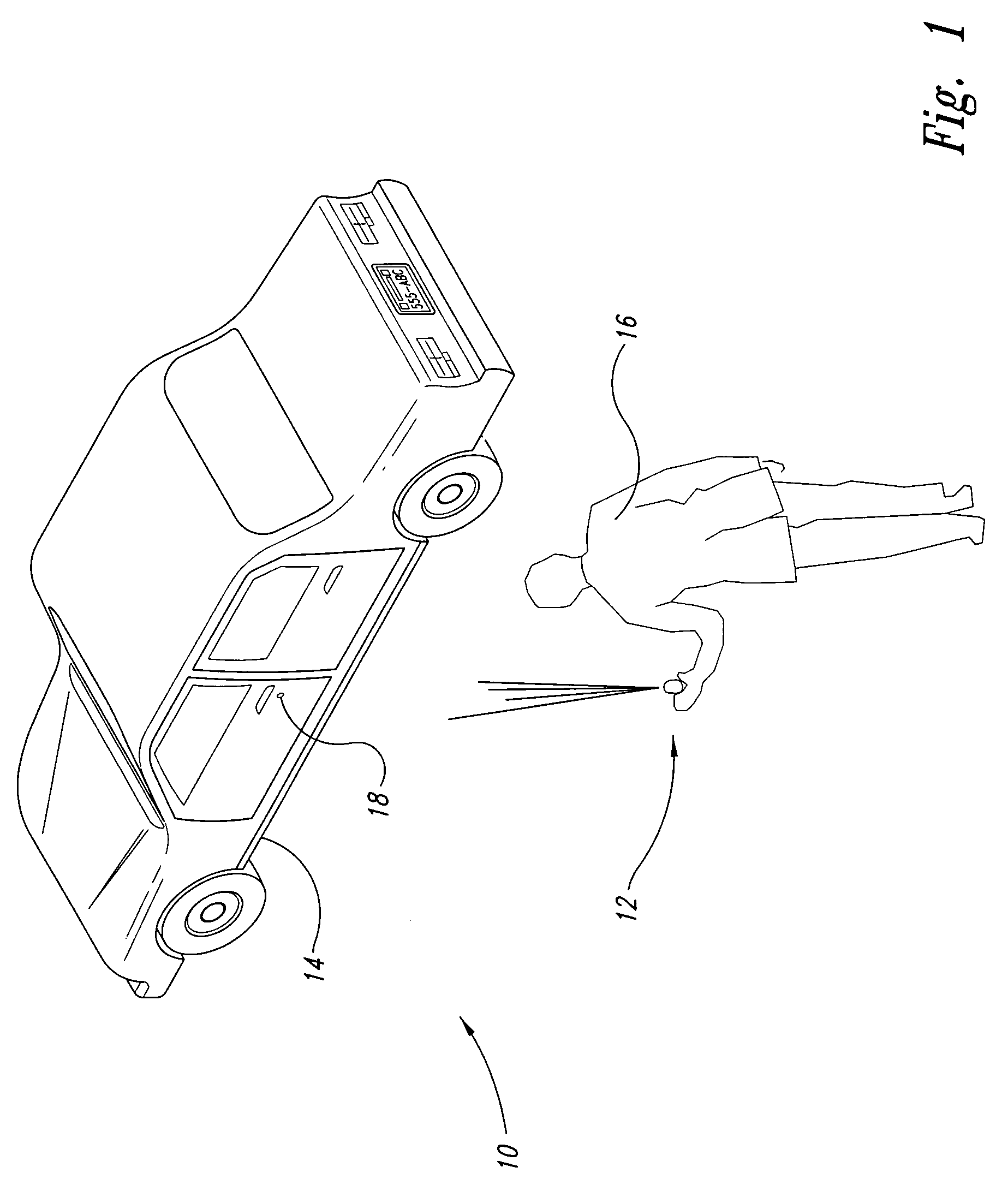
[0020]FIG. 1 illustrates a command system 10 according to principles of the present invention. The command system 10 includes a transmitting system 12 and a receiving system 14. The receiving system 14 includes an electronic receiver 18, usually embedded and not visible to the naked eye. In this case, the receiving system 14 is shown as an automobile. However, it could also be any other acceptable receiving device for which user security is desired, such as a garage, door, a home, a light or an office.

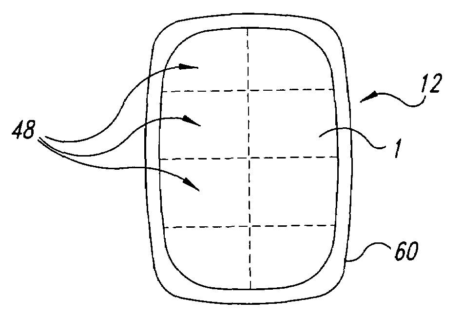
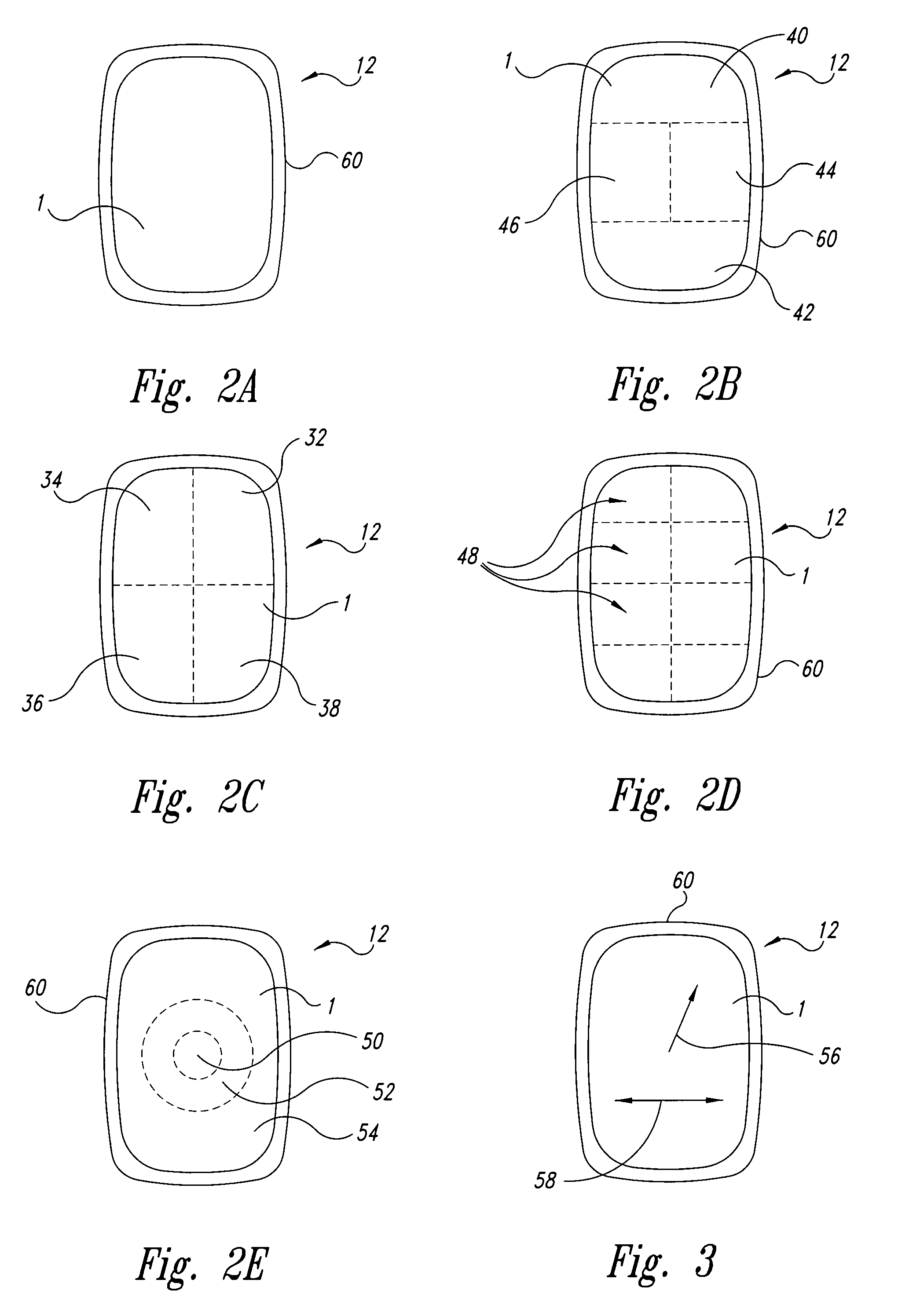
[0021]A user 16 uses the transmitting device 12 in order to send selected commands to the receiving device 14 and perform desired functions. The transmitting device 12 includes a fingerprint sensing system having a plurality of position-sensing devices as part of the array. Fingerprint sensing devices are well known in the art and any acceptable fingerprint or position-sensing device may be used. For example, an acceptable fingerprint sensing device is described in U.S. Pat. No. 5,973,...


PUM


Abstract

A substrate having a fingerprint sensing system usable as a command interface using finger movements. A user's fingerprint pattern is recognized and compared to previously stored reference patterns. If the fingerprint pattern matches a previously stored pattern, the user is then permitted to enter certain commands via the same interface system. For example, in the case of an automobile, a user may identify themselves with their fingerprint, and then perform such functions as unlocking the doors, setting the seat to a selected location, or even pre-starting the car prior to their entering the automobile. The very same devices which perform the fingerprint identification and sensing are also used for the input sensing and command recognition to perform the various commands. A user is thus able to securely control desired functions in an automobile, while being assured that an unauthorized user will not have access to the automobile, even as they were able to obtain the command interface device.

Description

TECHNICAL FIELD[0001]This invention is directed towards a command interface using the hand, and more particularly to a fingerprint sensor which also functions as a command input.BACKGROUND OF THE INVENTION[0002]Presently, automobiles are opened, closed, locked and unlocked by keys, door handles and other mechanical latching and unlatching devices. There is also available today for many automobiles a hand-held remote device with buttons thereon. Each button corresponds to a specific command. Currently, there is one button per command with the most common commands including lock doors, unlock doors, unlock trunk, set alarm, or honk horn. The user presses a specific button in order to implement and transfer the specific command to the automobile.[0003]Remote devices currently used do not distinguish one user from another. For example, if the owner of the car drops or loses the remote activation device, a passerby may pick up the remote, which usually has the key attached thereto. Any p...

Claims


Application Information

Patent Timeline
IPC IPC(8): G06F7/04E05B49/00B60R25/00E05B65/20G01B7/28G06F3/033G06F3/0354G06F3/041G06K9/00G06T1/00G07C9/00
CPCB60R25/25B60R25/252G06K9/00006G07C9/00158G07C9/00563G07C9/37G06V40/12
Inventor GUPTA, BHUSANKRAMER, ALAN
Owner APPLE INC
Why Eureka
Try Eureka