Method and apparatus for dynamic power management in a processor system

a technology of power management and processor system, applied in the field of processor system power management, can solve problems such as conflicting design goals and user intervention, and achieve the effect of different performance and/or power dissipation levels

Active Publication Date: 2007-07-03
APPLE INC
View PDF12 Cites 41 Cited by
  • Summary
  • Abstract
  • Description
  • Claims
  • Application Information

AI Technical Summary

Problems solved by technology

Typically, these design goals are in conflict.
Such an approach requires user intervention.

Method used


Image

  • Method and apparatus for dynamic power management in a processor system
  • Method and apparatus for dynamic power management in a processor system
  • Method and apparatus for dynamic power management in a processor system

Examples


Embodiment Construction

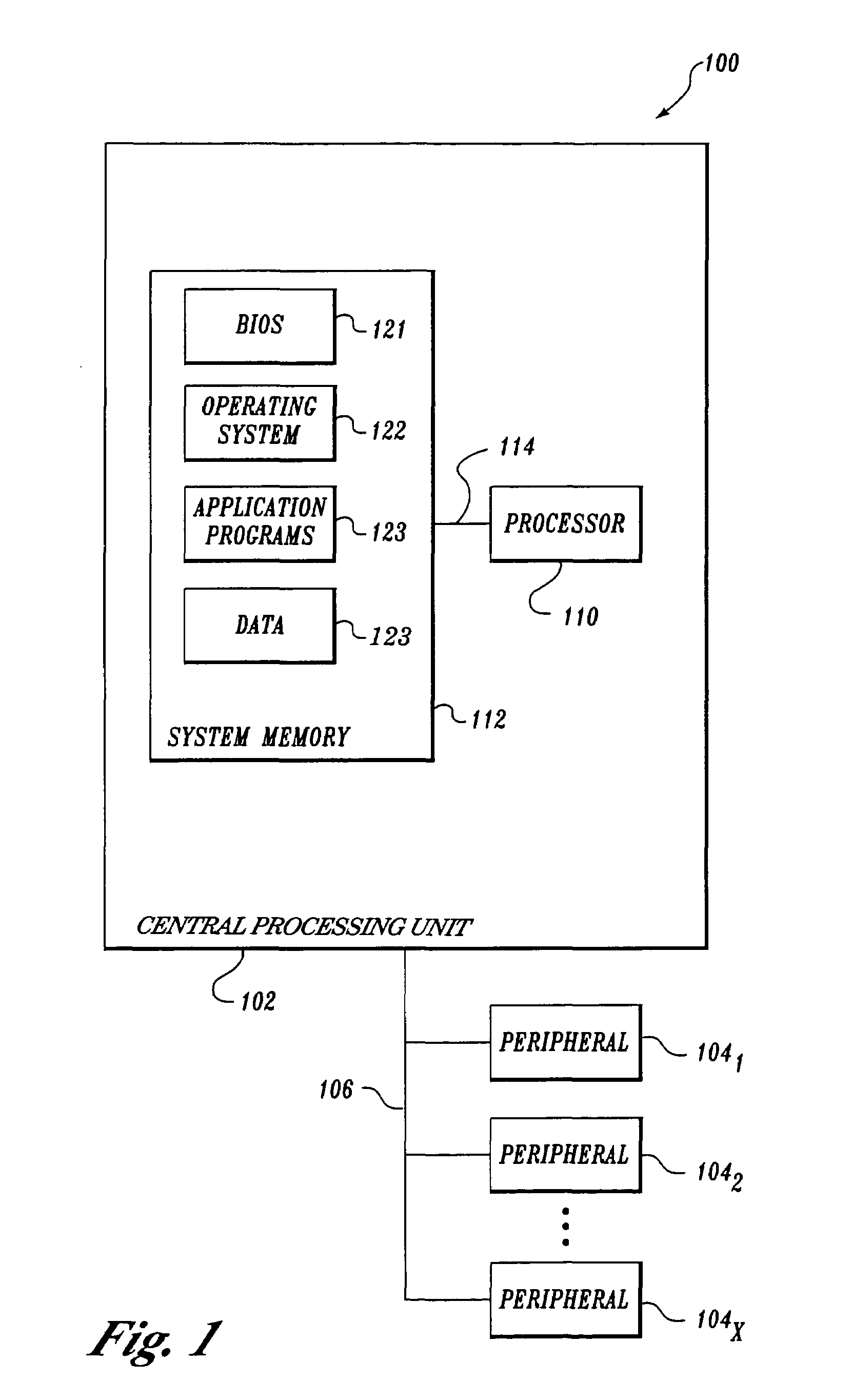
[0013]FIG. 1 illustrates an exemplary computing system 100 having dynamic power management according to one embodiment of the present invention. In this embodiment, computer system 100 includes a central processing unit 102 and peripherals 1041–104x. Central processing unit 102 is connected to peripherals 1041–104x via one or more buses 106. In some embodiments, central processing unit 102 may include a peripheral controller or “south bridge” (not shown) to communicate with peripherals 1041–104x.

[0014]In this embodiment, central processing unit 102 includes a processor 110 and a system memory 112 (typically implemented in RAM and ROM). Processor 110 is connected to system memory 112 via one or more buses 114. In some embodiments, a memory controller (not shown) may be used to transfer information between processor 110 and system memory 112. In other embodiments, central processing unit 102 can include multiple processors.

[0015]System memory 112 is typically used to store a basic inp...


PUM


Abstract

A dynamic power management system includes an operating system (OS) that causes a processor to operate in one of multiple run states that have different performance and / or power dissipation levels. The OS selects the run state in response to processor information (e.g., processor load) being monitored by the OS. The OS can predict future states of the processor information based on sampled processor information. The OS can take an average of the predicted and actual samples for comparison with a threshold to select a run state. The OS can track the number of consecutive saturated samples that occur during a selected window of samples. The OS can predict future processor information samples based on the number of consecutive saturated samples.

Description

FIELD OF THE INVENTION[0001]The field of invention relates generally to processor systems and, more specifically but not exclusively relates to power management for processor systems.BACKGROUND INFORMATION[0002]In designing processor systems such as used in computing platforms, the computing platform (including the processor) is commonly designed to increase performance. However, especially in mobile applications, computing platforms are also designed to reduce power consumption. Typically, these design goals are in conflict.[0003]One conventional solution to these goals is to provide a means for a user to switch the configuration of the computing platform between a high performance mode and a power conservation mode, as desired. For example, a computing platform may allow a user to select the desired mode via a hardware switch or via a menu and dialog box displayed by the computing platform. Such an approach requires user intervention.SUMMARY OF THE INVENTION[0004]In accordance wit...

Claims


Application Information

Patent Timeline
Patent Type & Authority Patents(United States)
IPC IPC(8): G06F1/00G06F1/26G06F1/32
CPCG06F1/3203Y02D10/00G06F1/26
Inventor DE CESARE, JOSHCULBERT, MICHAELCOX, KEITH
Owner APPLE INC
Why Eureka
Try Eureka