Centrifugal compressor

a centrifugal compressor and compressor technology, applied in the direction of machines/engines, liquid fuel engines, lighting and heating apparatus, etc., can solve the problems of affecting the performance of the compressor, the commercially unsuitable refrigerant is commercially unsuitable for direct replacement of the cfc refrigerant, and the refrigerant r134a is basically unsuitable for use with the existing compressor

Active Publication Date: 2007-07-10
DANFOSS AS
View PDF9 Cites 63 Cited by
  • Summary
  • Abstract
  • Description
  • Claims
  • Application Information

AI Technical Summary

Benefits of technology

[0006]An object of the present invention is therefore to provide an improved centrifugal compressor.

Problems solved by technology

This refrigerant, however, is commercially unsuitable as a direct replacement for the CFC refrigerants in existing hematic or semi-hematic machines because the chemical structure of R134A results in a performance loss of up to 30%.
Furthermore, the refrigerant R134A is basically unsuitable for use with existing compressors without major mechanical changes because the refrigerant is chemically incompatible with lubricants now available for mechanical bearings and other rotating or reciprocating pans of the compressors.
Another difficulty with current air conditioning systems is that, traditionally, small to medium refrigeration systems of a capacity in the range between 1 and 150 kilowatts use reciprocating, rotary or scroll compressors, which are relatively cheap to produce but are also relatively inefficient.
However, centrifugal compressors, which, basically, comprise a rotor sending air radially outwards into a stator under centrifugal action to create compression, involve high rotational speeds and are generally far more costly to produce and maintain.
In summary, the efficiency of the smaller equipment below 180 Tons is restricted by the available technology in the reciprocating, rotary, scroll and screw compressors.
While centrifugal machines can offer a higher efficiency in the lower capacity range, limitations on high rotational speed drives, and the cost thereof, inhibits their use.

Method used


Image

  • Centrifugal compressor
  • Centrifugal compressor
  • Centrifugal compressor

Examples


Embodiment Construction

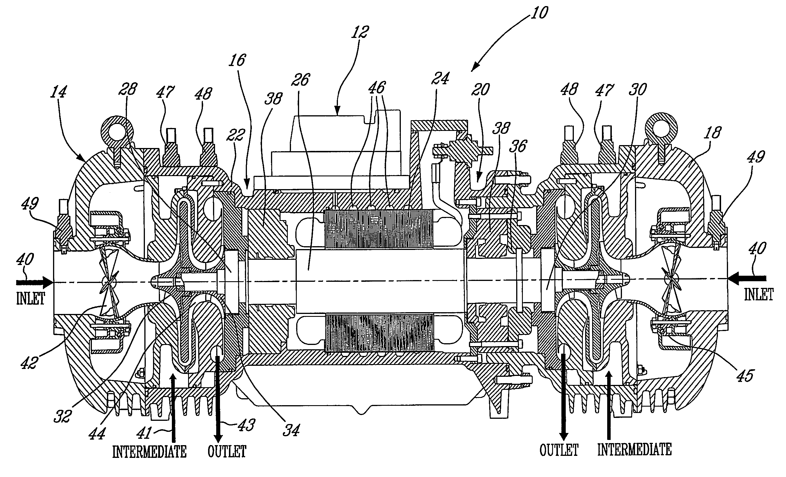
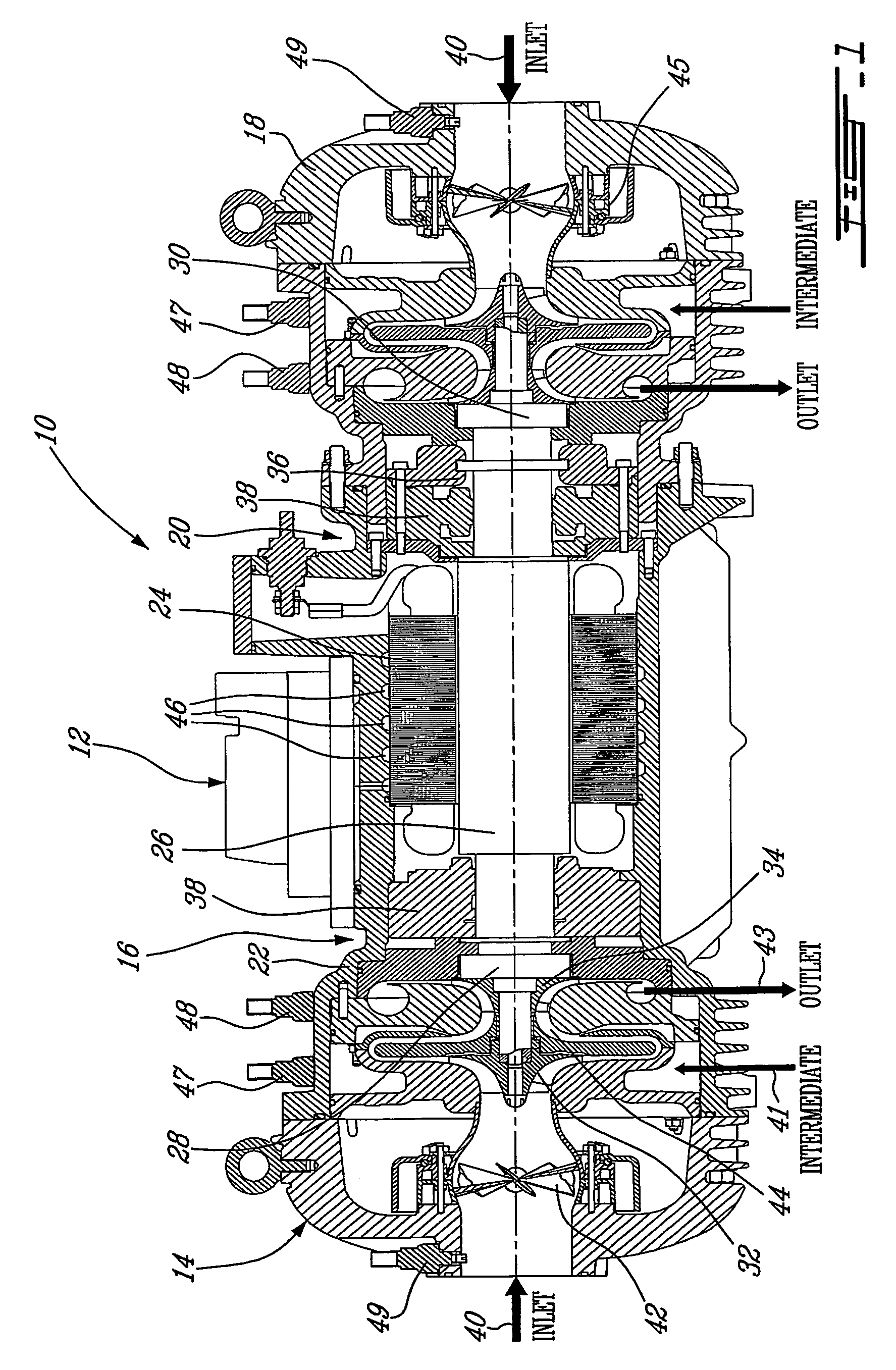
[0017]Generally stated, the present invention provides a centrifugal compressor comprising compressors mounted on a single common motor, thereby sharing a single drive, in such a way that the thrust at high RPM is balanced by using electromagnetic bearings.

[0018]More precisely, as illustrated in FIG. 1 of the appended drawings, a twin centrifugal compressor 10 in accordance with the present invention comprises an electric motor assembly 12, a first centrifugal compressor 14, and a second centrifugal compressor 18 within housing 22.

[0019]The first centrifugal compressor 14 is mounted to a first end portion 16 of the electric motor assembly 12 and the second centrifugal compressor 18 is mounted to a second end portion 20 of the electric motor assembly 12 in such a way that the electric motor assembly 12 is generally centrally located between the first and second centrifugal compressors 14 and 18.

[0020]The electric motor assembly 12 may be a high-speed electric motor assembly comprisin...


PUM

PropertyMeasurementUnit
speedaaaaaaaaaa
speedsaaaaaaaaaa
temperaturesaaaaaaaaaa

Abstract

A compact and efficient compressor is provided, based on using magnetic bearing technology, which can operate at high speed and comprises a reliable control system. The compressor of the present invention makes use of two separate compressors mounted on a single common motor, thus sharing a single drive. The balancing of the thrust at high RPM is improved by using a pair of electromagnetic bearings.

Description

FIELD OF THE INVENTION[0001]The present invention relates to centrifugal compressors. More precisely, the present invention is concerned with a twin centrifugal compressor.BACKGROUND OF THE INVENTION[0002]Compressors are used in refrigeration systems, environment control systems, air conditioning systems and the like. For convenience, the invention will be described with particular reference to air conditioning systems. Air conditioning systems utilize compressors of varying sizes ranging from very small compressors used in motor vehicles and domestic situations to compressors of up to thousands of Tons capacity used in commercial air-conditioning equipment.[0003]Refrigerants and air conditioning systems currently use a refrigerant R12 or a singular refrigerant that is a CFC or HCFC refrigerant, which is now known as potentially damaging to the environment, or R22, which is currently approved for use under the Montreal Protocol on the ozone layer until 2030 A.D for example. However,...

Claims


Application Information

Patent Timeline
Patent Type & Authority Patents(United States)
IPC IPC(8): F25B1/10F04D29/00F04D17/12F04D25/06F04D25/16F04D29/02F04D29/04F04D29/058F25B1/053F25B5/02F25B6/02F25B31/02
CPCF04D25/06F04D25/0606F04D25/16F04D29/023F04D29/058F25B1/053F25B5/02F25B6/02F05B2240/515F25B1/10F25B2400/061F05D2300/15F04D29/04F04D29/02
Inventor CONRY, RONALD DAVID
Owner DANFOSS AS
Why Eureka
Try Eureka