Method for managing a secure terminal

Inactive Publication Date: 2007-07-17
GEMPLU
View PDF18 Cites 23 Cited by
  • Summary
  • Abstract
  • Description
  • Claims
  • Application Information

AI Technical Summary

Benefits of technology

[0004]The object of the invention, in view of the very considerable development of transactions accessible with smart cards, is to ma

Problems solved by technology

The removable nature of these security circuits makes them insecure as regards defrauders who are suspected of wishing to know the secret thereof.
This is because the illegal use of a security circuit, without a terminal, is critical from the security point of view since it is possible for a

Method used


Image

  • Method for managing a secure terminal
  • Method for managing a secure terminal
  • Method for managing a secure terminal

Examples


Embodiment Construction

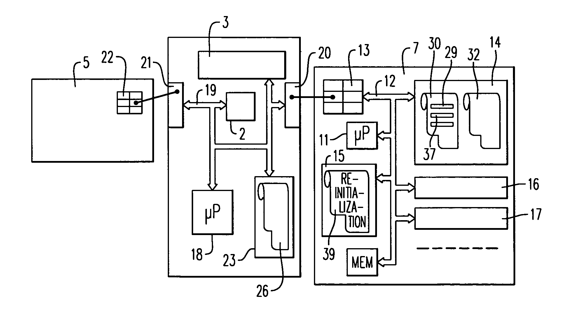
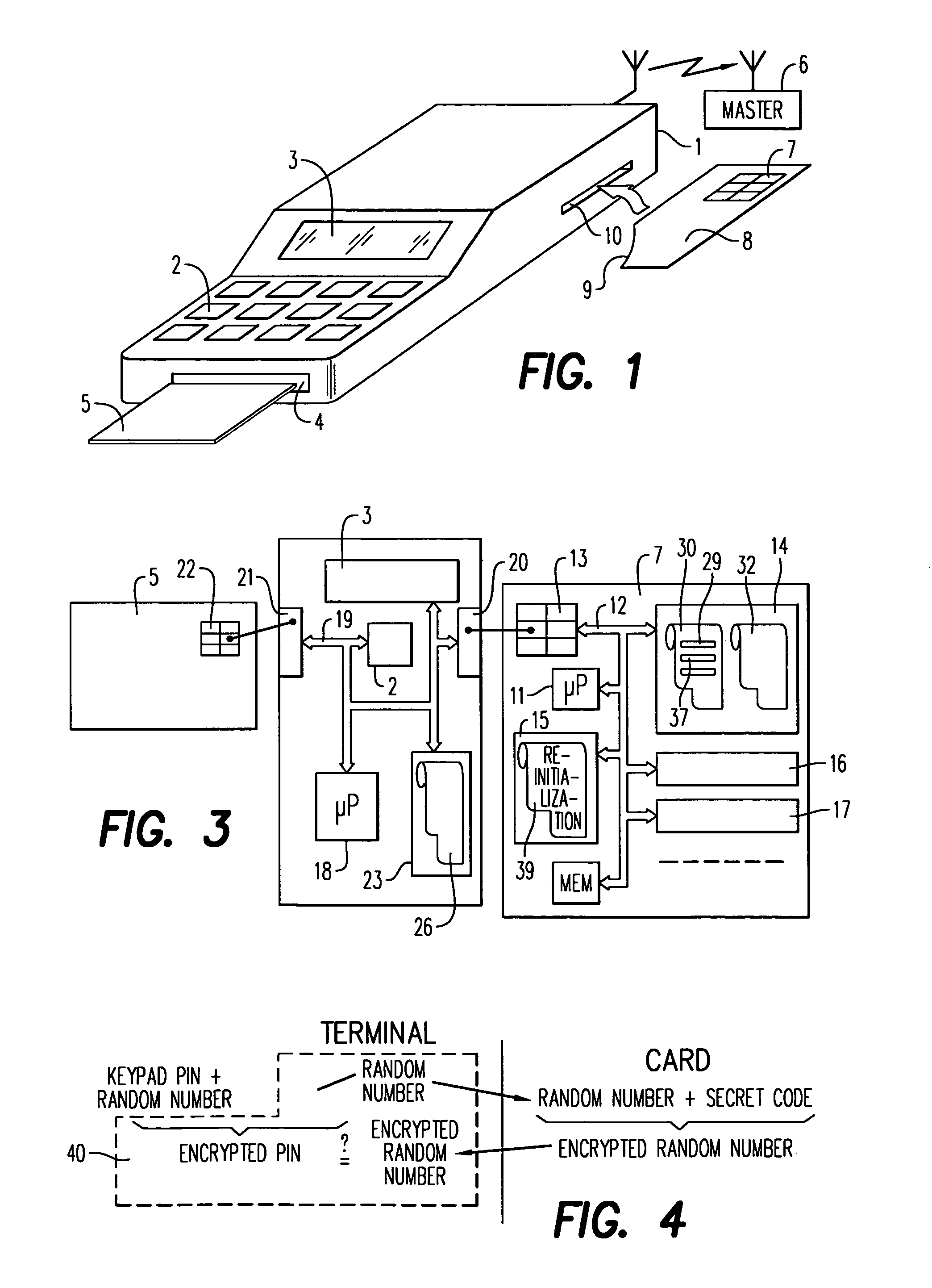
[0024]FIG. 1 shows a terminal 1 which can be used to implement the method of the invention. The terminal 1 has, in a known manner, preferably, a keypad 2, a screen 3 and a slot 4 for inserting therein a smart card 5 to be read with the reader terminal 1. The terminal 1 can furthermore be connected with a master system 6. The connection can notably be of the telecommunication type, the master system 6 being remote. The telecommunications can for example be radio. The terminal 1 is however capable of performing a certain number of operations autonomously and it is these which are mainly concerned. In a particular example shown in FIG. 1, the security circuit which is usable in the terminal1 is removable: it is a circuit 7 set in a portable smart object 8. The portable smart object 8 can have the same form as a smart card 5. Preferably, it has a different form with notably a geometric polarization part 9 for preventing users from putting it in incorrectly. The object 8 is intended to b...


PUM


Abstract

The invention concerns a method solving security problems resulting from the addition of a security circuit to a smart card reading terminal by providing said security circuit with means for counting the number of times the security circuit is activated for certain sensitive operations. When the total of said operations reaches a fixed value, the security circuit is prevented from operating until it is re-initialized again. Optionally, the circuit may have to be replaced by another.

Description

[0001]This application is based on French Patent Application No. 97 / 08813, filed on Jul. 10, 1997, which is incorporated by reference herein.BACKGROUND[0002]1. Field of the Invention[0003]The object of the present invention is a method of managing a secure terminal also referred to as a reader, and a security circuit for implementing the method. It relates to the field of so-called smart microcircuit cards and more generally the field of portable smart objects. This field is the one by which, with electronic circuits, either carriers of smart cards are authenticated, or information contents contained by the memories of these cards are authenticated, or finally payments, or credit increases, are carried out by modifying a number stored in the card and representing payment units or loyalty points.[0004]The object of the invention, in view of the very considerable development of transactions accessible with smart cards, is to make the read terminals, the available number of which is gr...

Claims


Application Information

Patent Timeline
IPC IPC(8): G06F21/00G06F21/20G06F21/24G06K19/00G06K7/00G06K17/00G07F7/10
CPCG06K7/0013G06K7/0091G06Q20/341G07F7/082G07F7/1008G07F7/1083
Inventor JEAN, LIONELOUVRAY, JEAN-CLAUDE
Owner GEMPLU
Why Eureka
Try Eureka