Adaptable electrical connector

a technology of electrical connectors and adapters, applied in the direction of couplings/cases, coupling device connections, securing/insulating coupling contact members, etc., can solve the problem of increasing manufacturing costs and achieve the effect of reducing heigh

Active Publication Date: 2007-07-24
ADVANCED CONNECTEK INC
View PDF2 Cites 7 Cited by
  • Summary
  • Abstract
  • Description
  • Claims
  • Application Information

AI Technical Summary

Benefits of technology

[0005]It is therefore one object of the present invention to provide an adaptable electrical connector comprising a plurality of conductors of cylindrical shape attached to a PCB by soldering so as to reduce height.

Problems solved by technology

This has the disadvantages of installing the cover 30, removing same, and increasing the manufacturing cost.

Method used


Image

  • Adaptable electrical connector
  • Adaptable electrical connector
  • Adaptable electrical connector

Examples


Embodiment Construction

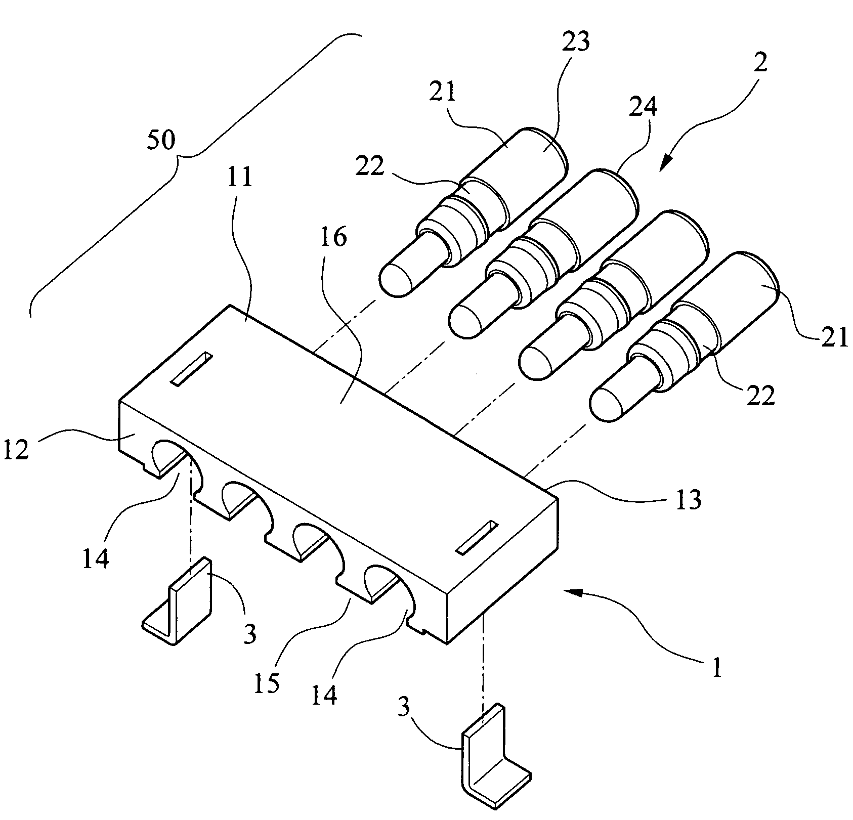
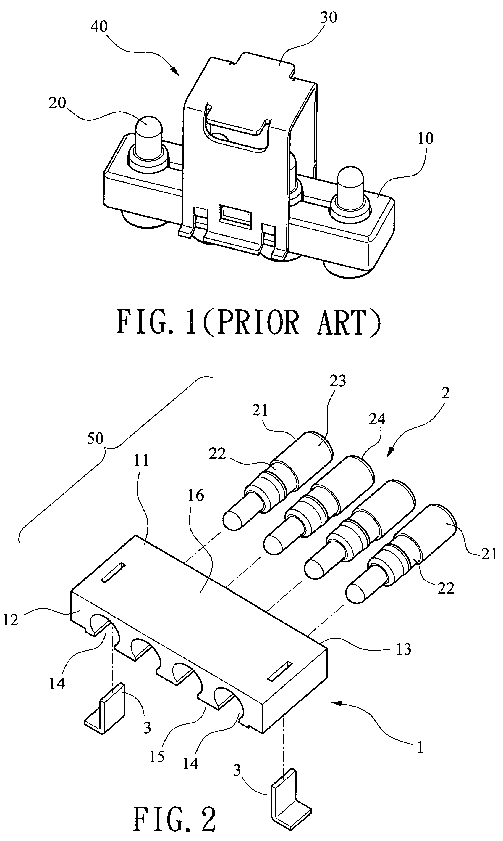
[0016]Referring to FIGS. 2 and 3, an adaptable electrical connector 50 in accordance with a preferred embodiment of the invention comprises an insulative seat 1, a plurality of conductors 2, and two L-shaped mounting plates 3 well known in the art. Each component is discussed in detailed below.

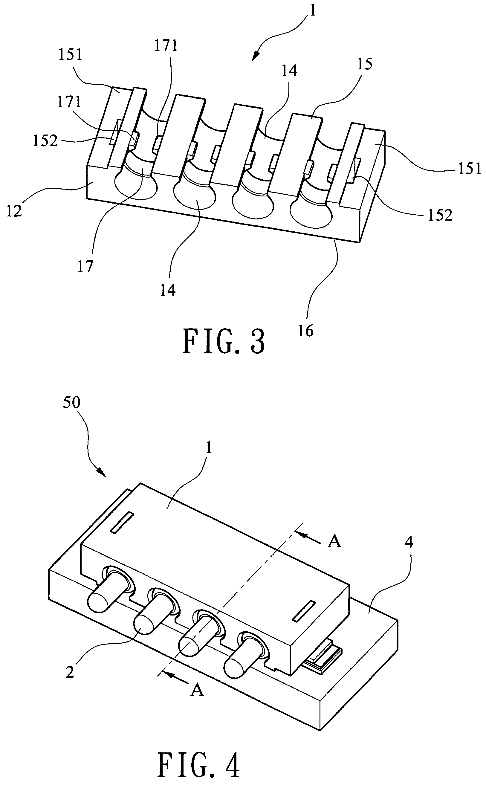
[0017]The seat 1 comprises a rectangular body 11 having a bottom 15 and a top 16 both having an area larger than that of the other four side faces (including a front end 12 and a rear end 13) of the body 11, and a plurality of lengthwise parallel grooves 14 through the bottom 15. On the bottom 15 there are provided a rectangular recess 151 at either side, and a channel 152 at either side having both ends open to the bottom 15 and the top 16 respectively. The groove 14 is open to the front end 12, the rear end 13, and the bottom 15 respectively. The groove 14 has an arc section. The groove 14 comprises an intermediate fastening member 17 including two opposite latches 171 on its opening to the ...


PUM


Abstract

An adaptable electrical connector is disclosed that includes a parallelepiped insulative seat including a front end, a rear end, a bottom, a top, and a plurality of lengthwise parallel grooves through the bottom, the groove being open to the front end, the rear end, and the bottom respectively; and a plurality of cylindrical conductors each including a rear cylindrical section; wherein the conductors are fastened in the grooves with the rear cylindrical sections exposed. The invention can decrease height and is adapted to mount on a PCB in either a first orientation or a second orientation perpendicular to the first orientation.

Description

BACKGROUND OF THE INVENTION[0001]1. Field of Invention[0002]The present invention relates to electrical connectors and more particularly to an adaptable electrical connector with reduced height and being capable of mounting on a PCB (printed circuit board) in either a first orientation or a second orientation perpendicular to the first orientation.[0003]2. Description of Related Art[0004]Adaptable electrical connectors are widely used in many kinds of electronic products (e.g., mobile phones, portable computers, etc.). A conventional adaptable electrical connector 40 is shown in FIG. 1 and comprises a rectangular insulative seat 10, a plurality of conductors 20, and a metal cover 30 of U-section. The cylindrical conductors 20 are physically and electrically connected to a PCB (not shown). The cover 30 is attached onto the seat 10 for the protection of the conductors 20. In use, a user has to remove the cover 30. This has the disadvantages of installing the cover 30, removing same, a...

Claims


Application Information

Patent Timeline
Patent Type & Authority Patents(United States)
IPC IPC(8): H01R13/40H01R13/518H01R13/52
CPCH01R9/091H01R13/518H01R12/716H01R12/7029H01R12/57
Inventor HOU, PIN-YUAN
Owner ADVANCED CONNECTEK INC
Why Eureka
Try Eureka