Prevention of precipitate blockage in microfluidic channels

a microfluidic channel and precipitate blockage technology, applied in the direction of flow mixers, positive displacement liquid engines, burettes/pipettes, etc., can solve the problems of creating precipitate blockages, causing precipitate blockages to come, and unwanted precipitate blockages can also arise through, so as to reduce precipitate blockages in microfluidic channels, and prevent or ameliorate precipitate blockages. , the effect of reducing the cross-section

Active Publication Date: 2007-07-24
CAPLIPER LIFE SCI INC
View PDF53 Cites 143 Cited by
  • Summary
  • Abstract
  • Description
  • Claims
  • Application Information

AI Technical Summary

Benefits of technology

[0005]The present invention provides methods, systems, kits, and devices for reducing, preventing or ameliorating precipitate blockages in microfluidic channels in microfluidic devices. Molecules, fluids, fluidic materials, etc. are flowed through specifically configured microfluidic elements (e.g., microchannels) in a microfluidic device. The specifically configured microfluidic elements comprise areas of enlarged cross-sectional geometry at the intersection of microfluidic elements, specifically arranged/intersected microchannels, allowing gradual/controlled dilution of precipitatable and/or precipitate inducing materials. The systems of the invention optionally also include features for applying an AC electric field orthogonal to the direction of fluid flow in the microchannels and/or microchannels structurally configured to permit application of an AC electric field orthogonal to the direction of fluid flow in a microchannel.
[0006]In one aspect, methods of preventing or ameliorating formation of precipitate blockages in a microfluidic element are provided. The methods comprise: flowing a first fluidic material through a first microchannel which channel comprises a first region and one more second region (which is downstream from the first region and is of greater cross-sectional area than the first or third region) and one or more third region (which is downstream from both the first region and the second region); flowing at least a second fluidic material through a second microchannel and into the second region of the first microchannel; and flowing the mixture of the first and second fluidic materials (and any precipitate) into the third region of the microchannel. In some embodiments, the cross-sectional area of the second region of the first microchannel is at least 2 times, at least 5 times, at least 10 times, at least 15 times, or at least 20 times or more greater in cross-sectional area than the first or third regions of the first microchannel. In yet other embodiments the cross-sectional area of the second region is great enough to prevent or ameliorate precipitate blockage of the microchannel by precipitate. In some embodiments, the second fluidic material comprises a buffer or water. Furthermore, other embodiments comprise applying an AC electric field orthogonal to the direction of fluid flow in the first microchannel.
[0007]In another aspect, the current invention comprises methods of reducing precipitate blockage in a microfluidic channel, comprising: flowing a first fluidic material into at least a first microchannel; flowing a selected amount of a second fluidic material into the first microchannel from at least a second microchannel (thus, diluting the first fluidic material and producing a precipitate at a concentration which permits flow of the fluidic materials and any precipitate through the first microchannel). In some embodiments, the first fluidic material comprises DMSO, and the second fluidic material comprises a buffer or water. In other embodiments, the first fluidic material is diluted by a select amount of the second fluidic material so as to dilute the first fluidic material by at least about 2-fold, at least about 3-fold, at least about 4-fold, or at least about 5-fold or more. In other embodiments the dilution of the first fluidic material is repeated (in either equal increments or in unequal increments) until a selected percent dilution of the first fluidic material is achieved. Additionally, the area of the first microchannel where the second fluidic material enters to dilute the first fluidic material is optionally of greater cross-sectional area than the areas both upstream and downstream of such enlarged area. Furthermore, other embodiments comprise wherein an AC electric field is applied orthogonal to the directi...

Problems solved by technology

However, because storage solutions, such as DMSO, can adversely affect certain types of assays, etc. and/or in order to present the molecule(s) in the storage solution (e.g., DMSO) in the correct concentration, such solution is typically diluted with other fluidic materials.
Unfortunately, sudden diluting of some storage solutions (e.g., DMSO) can cause precipitates to come out of solution and possibly create a precipitate blockage of a microchannel or other microelement in the microfluidic device.
Additionally, unwanted precipitate blockages can also arise through, e.g., pr...

Method used


Image

  • Prevention of precipitate blockage in microfluidic channels
  • Prevention of precipitate blockage in microfluidic channels
  • Prevention of precipitate blockage in microfluidic channels

Examples


Embodiment Construction

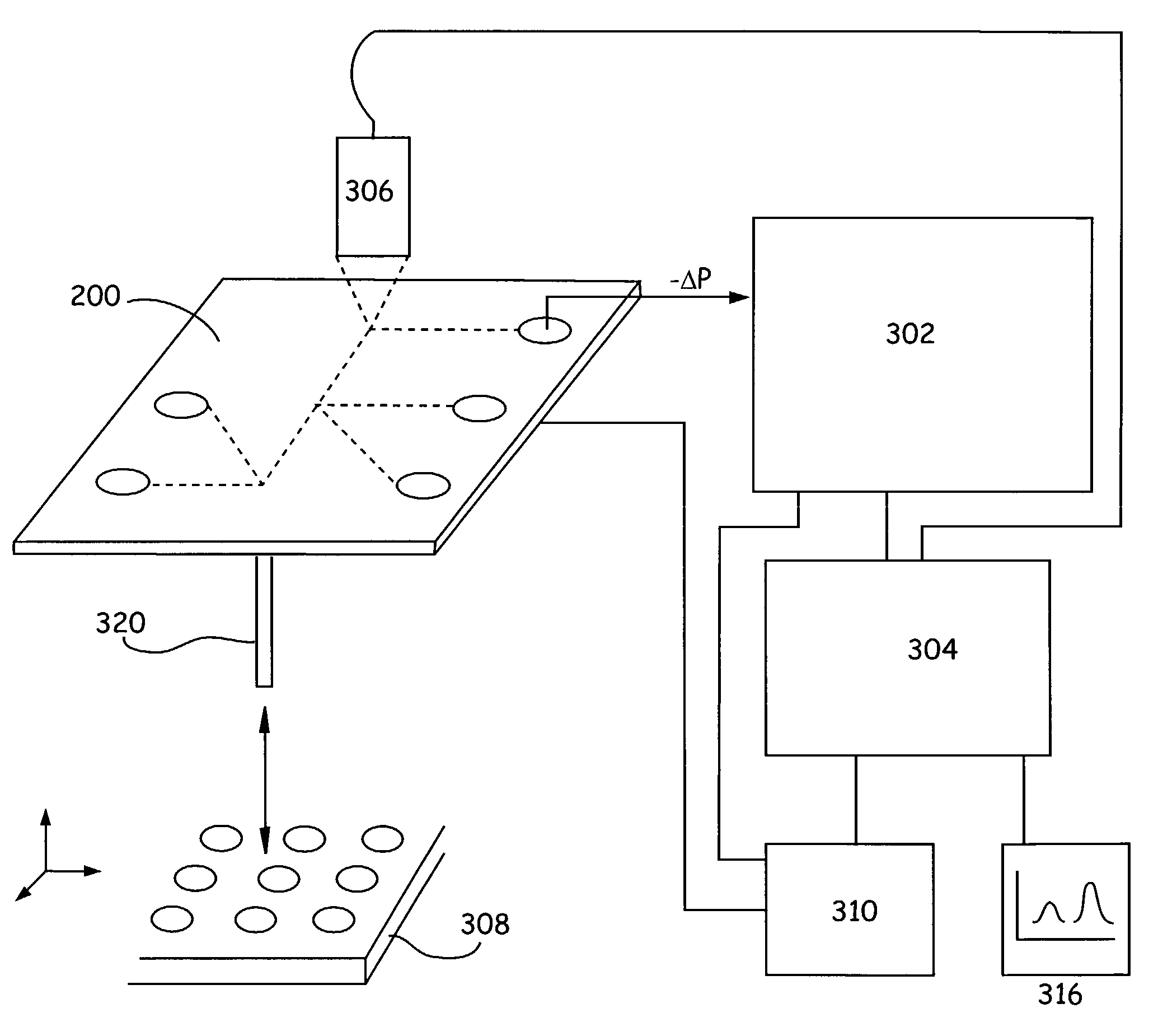
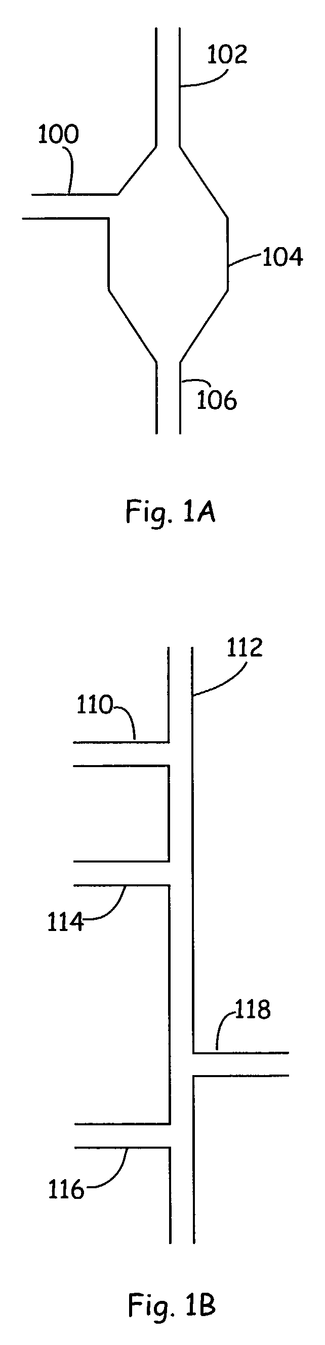
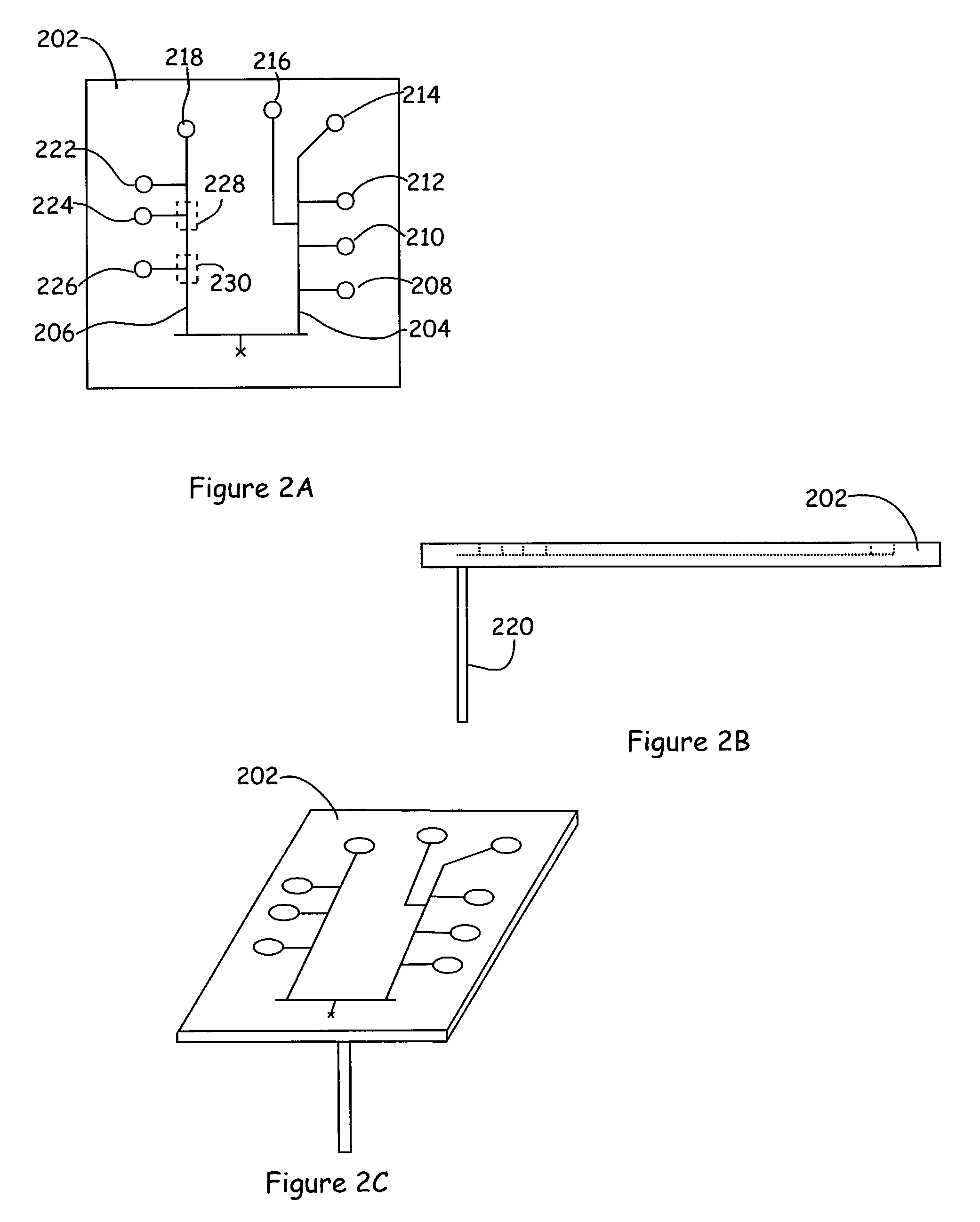
[0016]The methods and devices of the current invention directly address and solve problems associated with control and manipulation of fluidic material in microfluidic devices, especially dilution, mixing or transport of fluidic materials comprising precipitatable material, such as DMSO, or material comprising precipitate. Briefly, the invention provides devices and methods for: altering microchannel cross-sectional geometry in order to prevent formation of precipitate blockage of, e.g., microchannels; control of mixing together of fluidic materials (of either different types or of similar types) to, e.g., dilute a fluidic material in a manner which prevents / ameliorates formation of precipitate blockages of the microelements of the microfluidic device; applying an AC electric field orthogonal to the direction of fluid flow to help prevent / reduce precipitate sticking to the walls of the microchannel. As used herein, the term “cross-sectional geometry,”“channel geometry,”“cross-sectio...


PUM

PropertyMeasurementUnit
Concentrationaaaaaaaaaa
Areaaaaaaaaaaa
Electric fieldaaaaaaaaaa

Abstract

The present invention provides novel microfluidic devices and methods for preventing/ameliorating formation of precipitate blockages in microfluidic devices. In particular the devices and methods of the invention utilize microchannels of specific cross-sectional configuration and of specific arrangement as well as application of AC current orthogonal to the direction of fluid flow, in order to preventing/ameliorating formation of precipitate blockages in microfluidic devices.

Description

CROSS REFERENCE TO RELATED APPLICATIONS[0001]This application claims the benefit of U.S. Provisional Patent Application No. 60 / 338,040, filed Nov. 13, 2001, which is incorporated herein by reference in its entirety for all purposes.BACKGROUND OF THE INVENTION[0002]When carrying out chemical or biochemical analyses, assays, syntheses or preparations, a large number of separate manipulations are performed on the material(s) or component(s) to be assayed, including measuring, aliquotting, transferring, diluting, mixing, separating, detecting, incubating, etc. Microfluidic technology miniaturizes these manipulations and integrates them so that they can be executed within one or a few microfluidic devices. For example, pioneering microfluidic methods of performing biological assays in microfluidic systems have been developed, such as those described by U.S. Pat. Nos. 5,942,443 and 6,235,471.[0003]Of particular concern in numerous applications utilizing microfluidic devices is the dilutio...

Claims


Application Information

Patent Timeline
IPC IPC(8): B01L3/02B32B27/04B32B27/12B32B5/02G01N15/06
CPCB01F5/0471B01J19/0093B01L3/5027B01L3/502746B01F13/0059Y10T436/25625B01F2015/0221B01J2219/00247B01J2219/00783B01J2219/0086B01L7/52B01L2200/10B01L2200/14B01L2300/0816B01L2300/0867B01L2300/1805B01L2300/1822B01L2300/1833B01L2300/1838B01L2300/1861B01L2400/0415B01L2400/0487Y10T436/117497Y10T436/13Y10T436/11Y10T436/2575Y10T137/0357Y10T137/0329B01F25/314B01F33/30B01F35/715
Inventor CHOW, ANDREA W.
Owner CAPLIPER LIFE SCI INC
Why Eureka
Try Eureka