Antenna device having radiation characteristics suitable for ultrawideband communications
a radiation characteristic and ultrawideband technology, applied in the structure of radiating elements, elongated active elements, resonance antennas, etc., can solve the problem of not being able to perform the radiation in the frequency band required for ultrawideband communications, and achieve the effect of improving antenna characteristics and small siz
- Summary
- Abstract
- Description
- Claims
- Application Information
AI Technical Summary
Benefits of technology
Problems solved by technology
Method used
Image

Examples
first embodiment
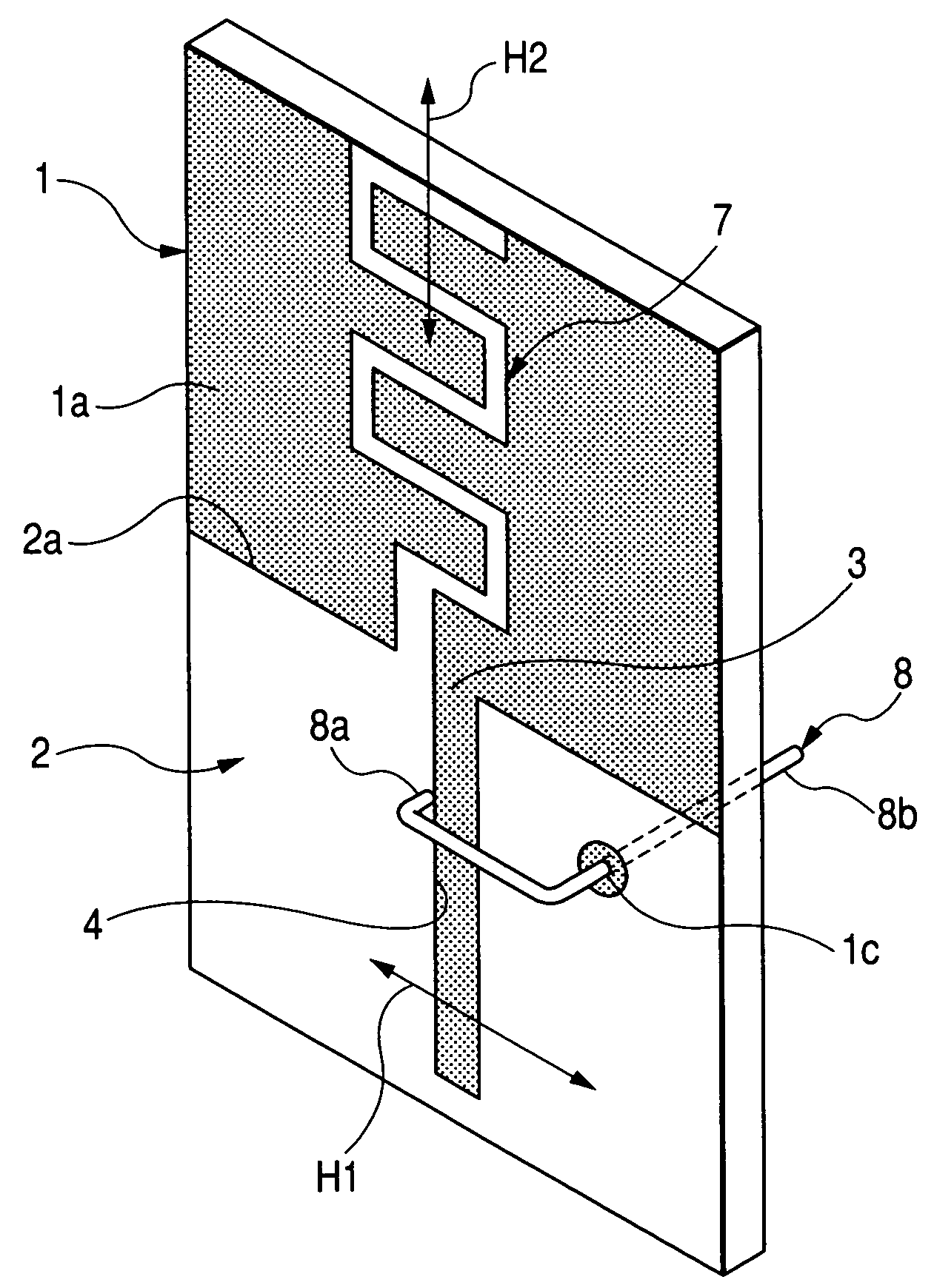
[0034]Referring to FIG. 1, an antenna device according to the invention is configured such that a conductor 2 is provided on one surface 1a of a dielectric substrate 1 having a rectangular plate shape by forming a conductive pattern, the conductive pattern being formed by etching copper foil or by coating conductive paste or the like. Also, the conductor 2 is provided with a meandering radiating conductor 7 which extends outward from one end 2a of the conductor 2 and has a length corresponding to a quarter wavelength of a first frequency. In addition, the conductor 2 is provided with a strip-shaped slot portion 4 that is formed by removing the conductor 2 inward from an opening 3 provided at the one end 2a and has a length corresponding to a quarter wavelength of a second frequency.
[0035]Further, a feed portion 8 is disposed to be perpendicular to the slot portion 4 and cross over the slot portion 4. One end portion 8a of the feed portion 8 is connected to the conductor 2, and the o...
second embodiment
[0044]Even in the second embodiment, the directions of the polarization planes H1 and H2 of the slot portion 4 and the radiating conductor 7 are perpendicular to each other.
[0045]Further, FIG. 3 illustrates an antenna device according to the third embodiment of the invention. In the antenna device according to the third embodiment of the invention, the dielectric substrate 1 is not provided, a conductor 2 and a radiating conductor 7 are formed by performing a pressing process for one metal plate, and a feed portion 8 is provided as a separate component.
[0046]Other configurations are the same as those in the first embodiment described above, and the same components are denoted by the same reference numerals and thus detailed explanation thereof will be omitted.
third embodiment
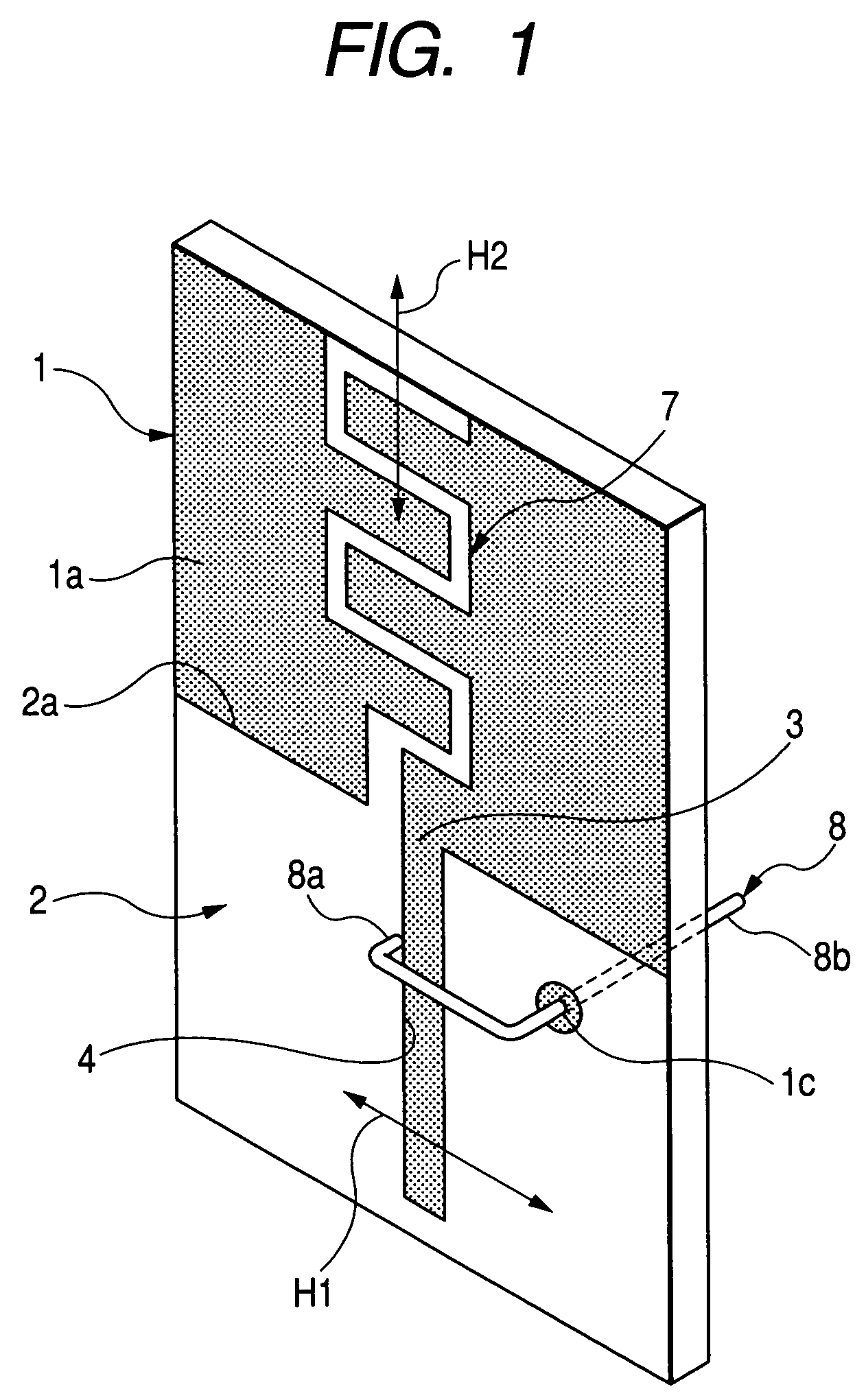
[0047]In the antenna device described above, the radiating conductor 7 has a meandering shape; however, as shown in FIG. 2, the radiating conductor 7 may be a strip-shaped conductor and may be bent at the end portion 2a of the conductor 2.
[0048]Further, the radiating conductor 7 may be bent along the longitudinal direction of the slot portion 4 with the end portion 2a of the conductor 2 as a reference line in a state in which the radiating conductor 7 and the conductor 2 are on the same plane, and thus the radiating conductor 7 may be disposed within a range of about 180° which is an angle closest to the conductor 2.
[0049]Furthermore, FIG. 4 illustrates an antenna device according to the fourth embodiment of the invention. In the antenna device according to the fourth embodiment of the invention, a feed portion 8 is integrally formed by bending one metal plate, with a conductor 2 and a radiating conductor 7, and the feed portion 8 is disposed to cross over a slot portion 4.
[0050]Ot...
PUM
 Abstract
Description
Claims
Application Information
 - R&D
- Intellectual Property
- Life Sciences
- Materials
- Tech Scout
- Unparalleled Data Quality
- Higher Quality Content
- 60% Fewer Hallucinations
Browse by: Latest US Patents, China's latest patents, Technical Efficacy Thesaurus, Application Domain, Technology Topic, Popular Technical Reports.
© 2025 PatSnap. All rights reserved.Legal|Privacy policy|Modern Slavery Act Transparency Statement|Sitemap|About US| Contact US: help@patsnap.com