Folding type communication terminal device

A communication terminal, foldable technology, applied in the direction of folded antenna, telephone communication, antenna support/installation device, etc., can solve the problem of not being able to work as an antenna, etc.

Inactive Publication Date: 2007-08-08
PANASONIC CORP
View PDF1 Cites 8 Cited by
  • Summary
  • Abstract
  • Description
  • Claims
  • Application Information

AI Technical Summary

Problems solved by technology

As a result, when the first and second housings 101 and 102 are opened, broadband characteristics are provided; and when the first and second housings 101 and 102 are folded, due to the flow to the antenna (plate element 107) The reason why the vector of the high-frequency current and the high-frequency current flowing to the ground of the antenna (the second case 102) cancels out is that it cannot work as an antenna

Method used


Image

  • Folding type communication terminal device
  • Folding type communication terminal device
  • Folding type communication terminal device

Examples


no. 1 approach

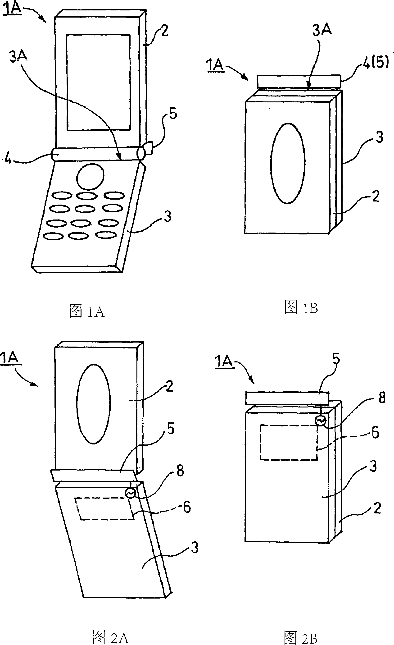
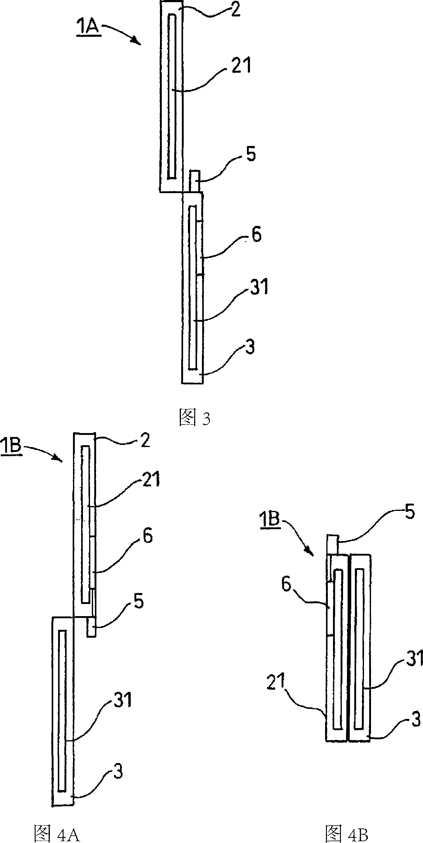
[0048] 1 and 2 show a foldable communication terminal device 1A according to a first embodiment of the present invention. This foldable communication terminal device 1A includes: a rectangular upper casing 2 as the first casing, a rectangular lower casing 3 as the second casing, connecting the upper and lower casings 2, 3 and making it freely foldable (rotating) hinge part 4, and first antenna 5.

[0049] Wherein, inside the upper case 2 , as shown in FIG. 3 , a first printed circuit board 21 is provided that substantially completely covers the upper case 2 . On the other hand, in the lower case 3, as shown in FIG. The wireless unit 6 is composed of a transmitting and receiving circuit, and is electrically connected to the first antenna 5 through the power supply unit 8 . The first antenna 5 has an elongated shape, and is provided in a protruding state along an upper end surface (edge ​​portion) 3A of the lower case 3 facing the hinge portion 4 . In addition, the first ante...

no. 2 approach

[0057] Next, a communication terminal device according to a second embodiment of the present invention will be described. In addition, in this embodiment, the same parts as those in the first embodiment are assigned the same reference numerals to avoid duplication of description.

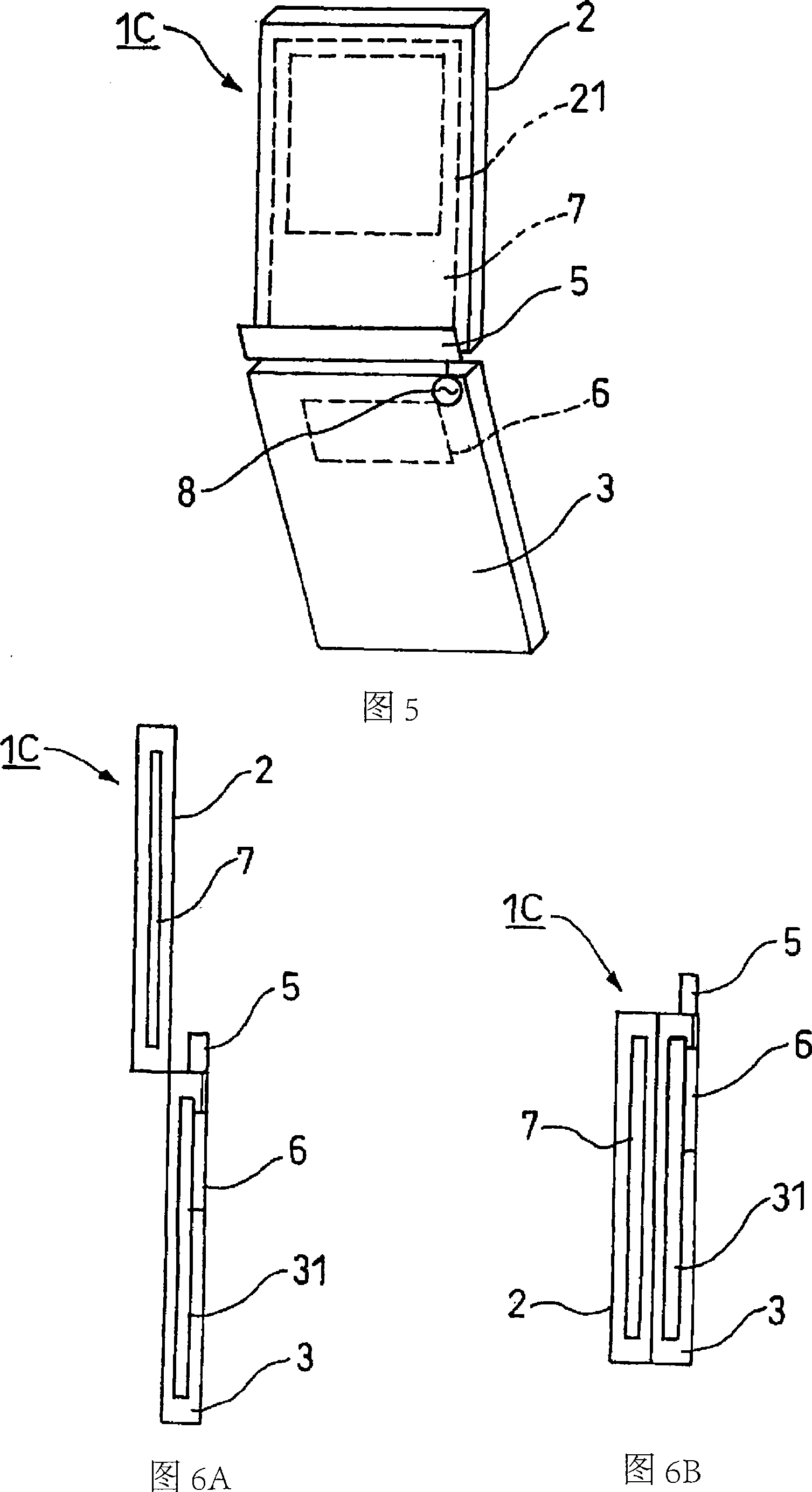
[0058] 5 and 6 show a communication terminal device 1C according to a second embodiment of the present invention. This communication terminal device 1C differs from the first embodiment in that not only is the first antenna-5 protruding along the upper end surface (edge ​​portion) 3A of the lower case 3 facing the hinge portion 4, but The second antenna 7 is disposed on the first printed substrate 21 inside the upper casing 2 . In addition, the second printed circuit board 31 provided inside the lower case 3 includes the wireless unit 6 electrically connected to the first antenna 5 as in the first embodiment. On the other hand, the second antenna 7 is formed to be larger than the first printed cir...

no. 3 approach

[0066] Next, a communication terminal device according to a third embodiment of the present invention will be described. In addition, in this embodiment, the same parts as those in the first embodiment are assigned the same reference numerals to avoid duplication of description.

[0067] 8 and 9 show a communication terminal device 1E according to a third embodiment of the present invention. The communication terminal device 1E is provided with a first antenna 5 along the upper end surface 2A (edge ​​portion) of the upper case 2 and is provided on The first printed circuit board 21 inside the upper case 2 includes the wireless part 6 . In addition, inside the lower case 3 , a second printed circuit board 31 is provided in the same manner as in the first embodiment.

[0068] The operation of communication terminal device 1E configured as described above will be described in detail with reference to FIG. 9 .

[0069] (1) When the upper casing 2 and the lower casing 3 are opene...


PUM


Abstract

A communication terminal device provided with foldable first case and second case has wide band antenna characteristics in both cases where the cases are open and folded. The folding type communication terminal device is provided with the upper and lower cases (2, 3) which can be folded through a hinge part, and an antenna (5) provided on the lower case (3). The antenna (5) is provided along an edge plane (3A) on an upper part side having contact with the hinge part of the lower case (3), and is provided with a conductor on the upper case (2) having no antenna, and a second printed board (31) which couples with the antenna (5) in high frequency to operate as antenna when the upper and lower cases (2, 3) are opened and transmits / receives electromagnetic waves.

Description

technical field [0001] The present invention relates to foldable communication terminal devices such as foldable mobile phones. Background technique [0002] An example of a conventional foldable communication terminal device is shown in FIG. 14 . This foldable communication terminal device includes a first housing 101, a second housing 102, and a hinge portion 103 that can fold and connect the first and second housings. In addition, such a foldable communication terminal device is generally of the type in which the antenna 104 is provided on the first case 101 as shown in FIG. The type of the antenna 104 and the like are set. [0003] In addition, various types of antennas applied to such folding communication terminal devices are known. For example, a pull-out whip antenna has a wide frequency band, but the pull-out whip antenna prevents it from being used. In addition, the helical wire antenna not only has a narrow frequency band, but also because the antenna is protr...

Claims


Application Information

Patent Timeline
Patent Type & Authority Applications(China)
IPC IPC(8): H01Q1/24H04M1/02H01Q1/08
CPCH04M1/0214H01Q1/242H01Q1/08
Inventor 中里光晴菊地弘准渡边聪
Owner PANASONIC CORP
Why Eureka
Try Eureka