Gap butterfly antenna with passive device

A no-feed, bow-tie technology, applied in the direction of slot antennas, antenna arrays powered separately, electrical components, etc., can solve the problem of no further improvement in antenna performance

Inactive Publication Date: 2003-04-02
MINEMITSU DENSHI
View PDF0 Cites 9 Cited by
  • Summary
  • Abstract
  • Description
  • Claims
  • Application Information

AI Technical Summary

Problems solved by technology

[0015] Although it has the advantage of simple structure, there is no room for further improvement of antenna performance

Method used


Image

  • Gap butterfly antenna with passive device
  • Gap butterfly antenna with passive device
  • Gap butterfly antenna with passive device

Examples


Embodiment Construction

[0041] Image 6 It is a perspective view of an embodiment of the slot bowtie antenna of the present invention.

[0042] next to Image 6 with the aforementioned Figure 5 (Known example) The difference will be described.

[0043] The elongated passive element 16 is parallel to the y-axis and straddles the bow-tie-shaped elongated hole. The passive element 16 is mounted on the metal plate 13 via an insulating plate 17 . is electrically insulated.

[0044] Symbols 15c and 15d are feeding points, which are connected to the coaxial cable 8 . 8c is a coaxial cable connector.

[0045] The reflection plate 20 is parallel to the aforementioned metal plate 13 and supported by spacers 18 .

[0046] When there is no reflector 20, the slotted bow-tie antenna of this example has directivity in the directions of arrows Z and Z', and when the reflector 20 is provided, it only has unidirectionality in the direction of arrow Z.

[0047] As in this embodiment ( Image 6 ), perpendicula...


PUM


Abstract

The invention relates to an antenna for communication between M Hz to LG Hz. The antenna is used for solving thin type and high gain problems and performing improvement of widening frequency width of tuning frequency. The antenna athwart provides an electric insulative no-feeding member (16) in a y-axes direction for a slot type bow tie antenna member (19). And the antenna is used for a portable wireless communication machine and a wireless LAN (local area network).

Description

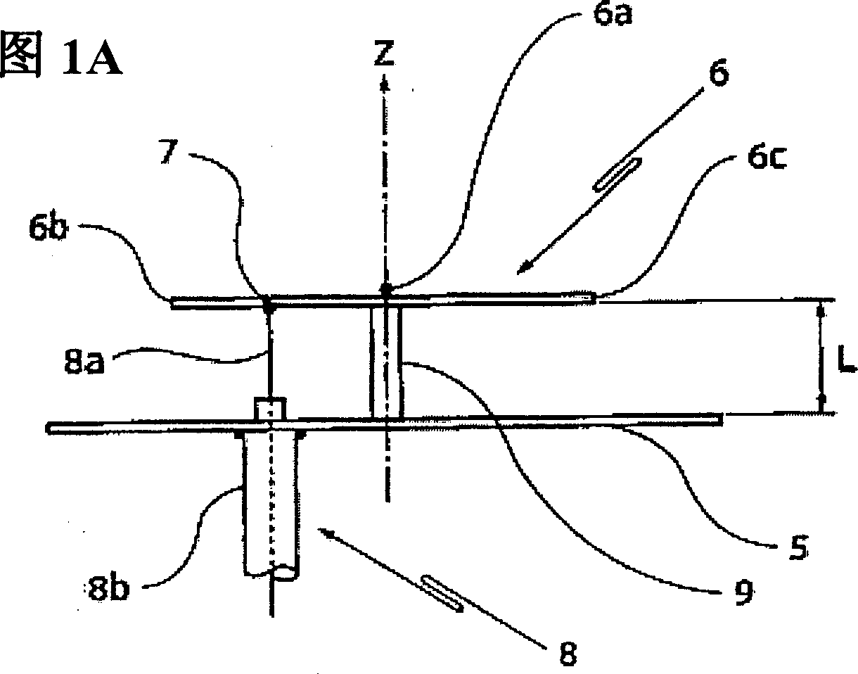
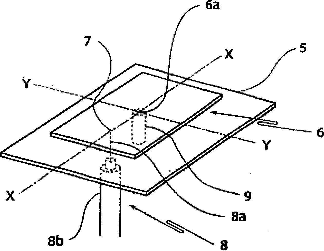
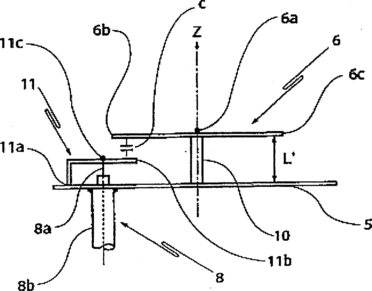
technical field [0001] The present invention relates to an antenna for transmitting and receiving megacycle to gigacycle radio waves, and more particularly to an antenna device having a thin structure, improved directivity, and low-cost manufacture. Background technique [0002] Figure 1A is a side view of a known planar antenna with a reflector, Figure 1B for its stereogram. (Figure 1A and Figure 1B Reference together) symbol 6 shows a radiation plate, and symbol 5 shows a reflector. [0003] 6a is the central part of the radiation plate 6, the impedance at this point is 0, the current value is the largest, and the voltage value is 0. [0004] The impedance changes continuously from the central portion 6a to the end portion 6b. The point 7 having an impedance of 50Ω is used as a feeding point, and is connected to the central conductor 8a of the coaxial cable 8 . The outer conductor 8b of the above-mentioned coaxial cable 8 is connected to the above-mentioned reflecting...

Claims


Application Information

Patent Timeline
Patent Type & Authority Applications(China)
IPC IPC(8): H01Q5/00H01Q5/378H01Q13/10H01Q21/06
CPCH01Q21/064H01Q13/106H01Q5/0062H01Q5/378
Inventor 江头良水
Owner MINEMITSU DENSHI
Why Eureka
Try Eureka