Powered step device of motor vehicle

a technology of motor vehicles and step devices, which is applied in the direction of steps, vehicle components, transportation and packaging, etc., can solve the problems of reducing the aesthetic value of the powered step device, damage to the supporting arms, and high possibility of collision with stones

Inactive Publication Date: 2009-04-07
MITSUI KINZOKU ACT
View PDF7 Cites 62 Cited by
  • Summary
  • Abstract
  • Description
  • Claims
  • Application Information

AI Technical Summary

Benefits of technology

[0007]That is, even in the retracted position, the two supporting arms are exposed to the outside of the device due to their inherent construction. Such projection of the supporting arms outside of the device tends to induce a high possibility of collision with stones or the like that would be kicked or smashed by the front road wheels of the vehicle under running. Of course, such collision damages the supporting arms. Furthermore, the exposed appearance of the supporting arms lowers the aesthetic value of the powered step device.
[0008]Furthermore, the powered step device of the Japanese Patent has a relatively thicker construction because the essential parts of the device are arranged to overlap one another in a vertical direction. Furthermore, due to inherent construction of the device, an increase in thickness of each part is inevitably necessary for providing the step device with a sufficient mechanical strength. However, the thickness increase of the parts brings about not only increase in weight and size but also increase in cost of the step device.
[0009]It is therefore an object of the present invention to provide a powered step device of a motor vehicle, which is free of the above-mentioned drawbacks.
[0011]In accordance with the present invention, there is provided a powered step device of a motor vehicle, of which pivoting mechanism is thinner in construction.
[0012]In accordance with a first aspect of the present invention, there is provided a powered step device of a vehicle, which comprises a base member that is adapted to be connected to a vehicle body; a pivoting mechanism held by the base member, the pivoting mechanism being horizontally movable between a first position wherein a given part thereof takes a retracted position relative to the base member and a second position wherein the given part takes a projected position relative to the base member; a step plate connected to the given part of the pivoting mechanism, so that the first and second positions of the pivoting mechanism induce retracted and projected positions of the step plate relative to the base member; an electric actuator that moves the pivoting mechanism with electric power; and a guard member fixed to the base member in a manner to cover and protect the pivoting mechanism.

Problems solved by technology

Such projection of the supporting arms outside of the device tends to induce a high possibility of collision with stones or the like that would be kicked or smashed by the front road wheels of the vehicle under running.
Of course, such collision damages the supporting arms.
Furthermore, the exposed appearance of the supporting arms lowers the aesthetic value of the powered step device.
Furthermore, due to inherent construction of the device, an increase in thickness of each part is inevitably necessary for providing the step device with a sufficient mechanical strength.
However, the thickness increase of the parts brings about not only increase in weight and size but also increase in cost of the step device.

Method used


Image

  • Powered step device of motor vehicle
  • Powered step device of motor vehicle
  • Powered step device of motor vehicle

Examples


Embodiment Construction

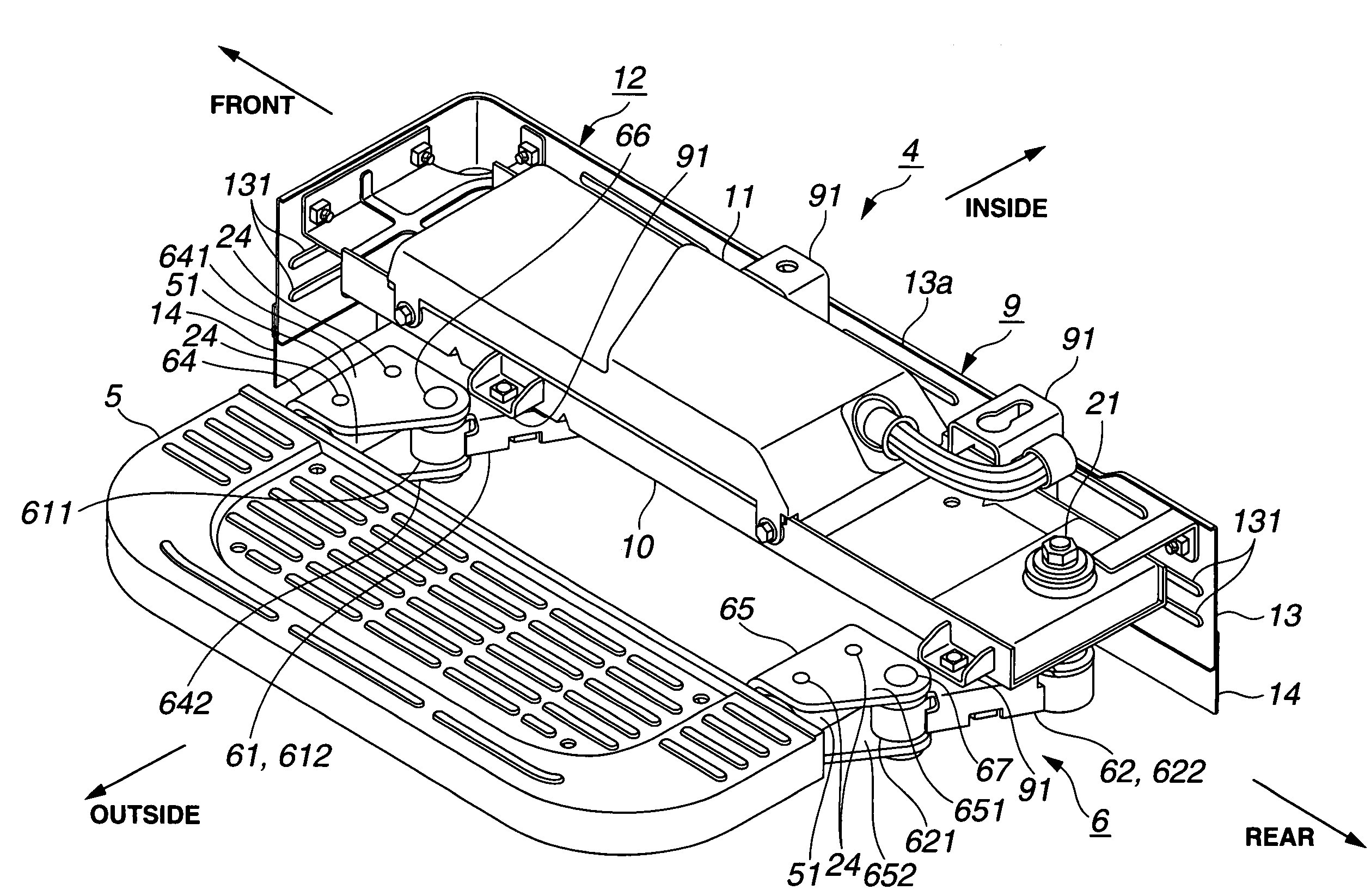
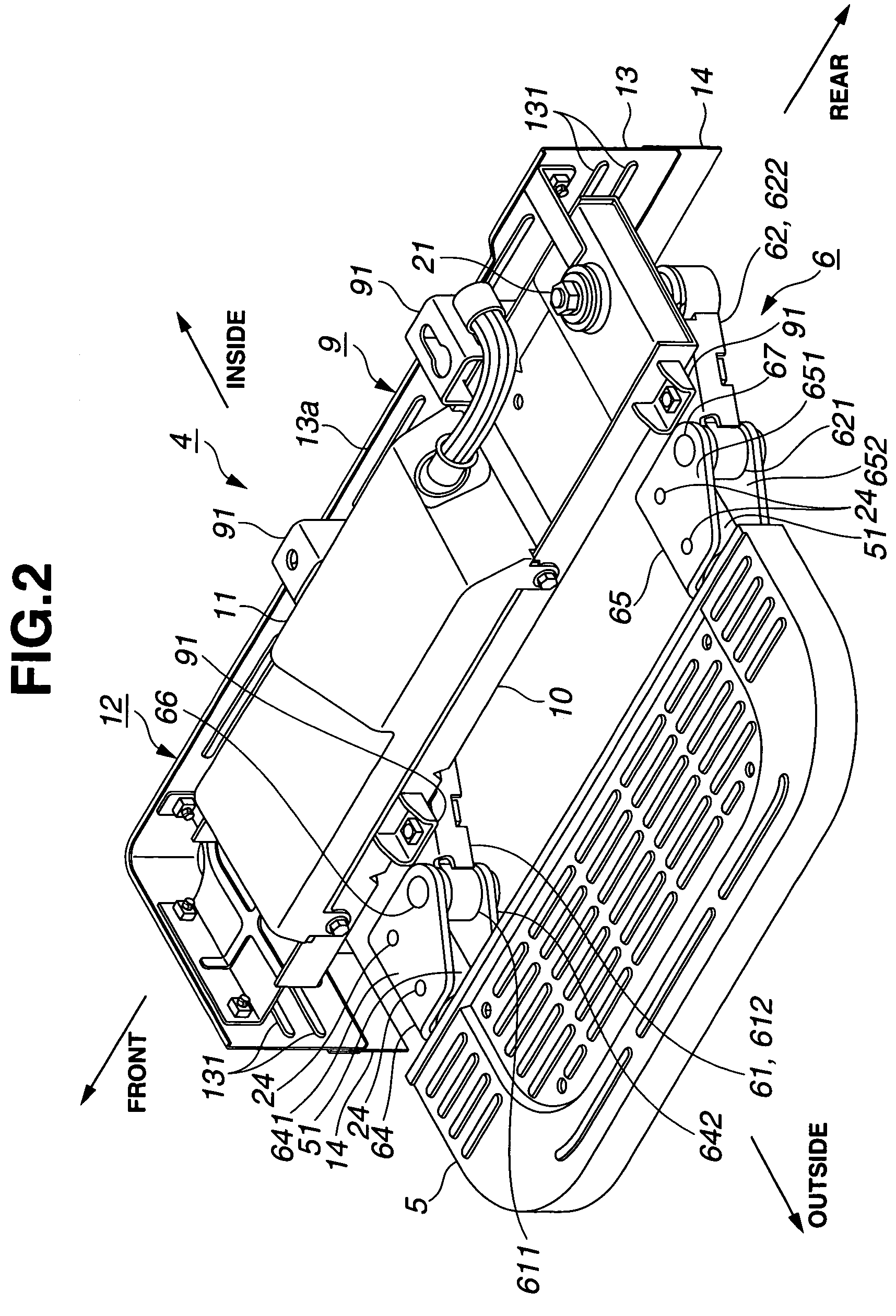
[0024]In the following, a powered step device 4 of a motor vehicle of the present invention will be described with reference to the accompanying drawings.

[0025]For ease of understanding, various directional terms, such as, right, left, upper, lower, rightward and the like are used in the following description. However, such terms are to be understood with respect to only a drawing or drawings on which a corresponding part or parts are shown.

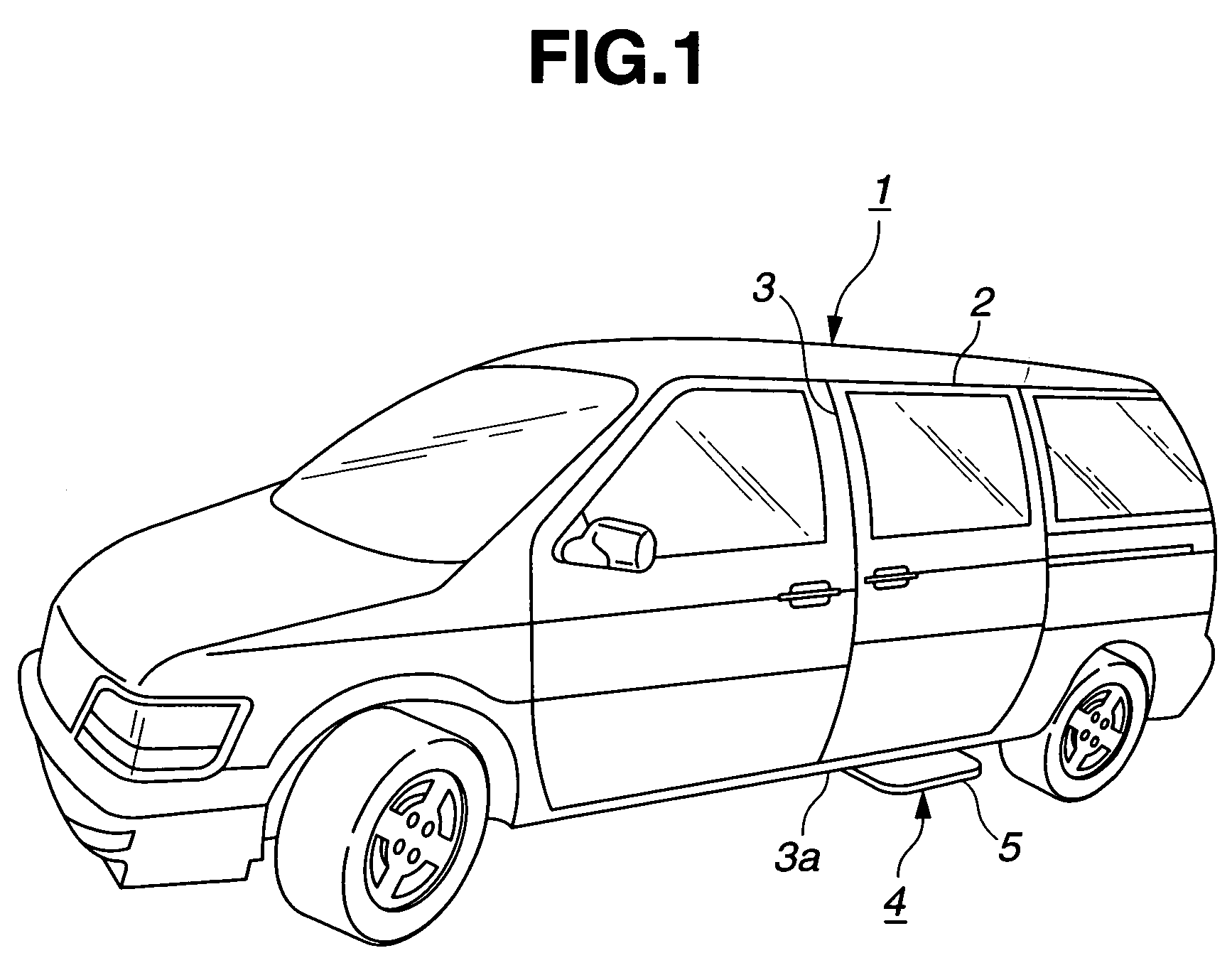
[0026]Referring to FIG. 1, there is shown by example a van-type motor vehicle 1 to which the powered step device 4 of the invention is practically applied. The vehicle 1 is equipped with a slide door 2 that moves forward to close a door opening 3 and moves rearward to open the door opening 3.

[0027]The powered step device 4 of the invention is connected to a floor panel 3a of the vehicle 1 at a position just below the door s opening 3. As will become apparent as the description proceeds, when the slide door 2 is opened, a step plate 5 of the step ...


PUM


Abstract

A powered step device of a vehicle comprises a base member that is adapted to be connected to a vehicle body; a pivoting mechanism held by the base member, the pivoting mechanism being horizontally movable between a first position wherein a given part thereof takes a retracted position relative to the base member and a second position wherein the given part takes a projected position relative to the base member; a step plate connected to the given part of the pivoting mechanism, so that the first and second positions of the pivoting mechanism induce retracted and projected positions of the step plate relative to the base member; and an electric actuator that moves the pivoting mechanism with electric power. The powered step device further comprises a guard member that is fixed to the base member in a manner to cover and protect the pivoting mechanism.

Description

BACKGROUND OF THE INVENTION[0001]1. Field of the Invention[0002]The present invention relates in general to a step device that is installed below a door opening of a motor vehicle for assisting the passengers who get on and off the vehicle, and more particularly to a step device of powered retractable type having a step plate that can be retracted inside the vehicle with electric power when not in use.[0003]2. Description of the Related Art[0004]Hitherto, various powered step devices of motor vehicles have been proposed and put into practical use particularly in the field of van type vehicles, buses and the like.[0005]One of such known powered step devices is shown in Laid-open Japanese Patent Application (Tokkaihei) 11-227528 filed on Feb. 17, 1998 (matured to Japanese Patent 3612418 on Oct. 29, 2004), which generally comprises two supporting arms that are pivotally connected to the vehicle body, a step plate that is held by the supporting arms and an electric drive mechanism that ...

Claims


Application Information

Patent Timeline
Patent Type & Authority Patents(United States)
IPC IPC(8): B60R3/02
CPCB60R3/02
Inventor OKUYAMA, KEIICHIRO
Owner MITSUI KINZOKU ACT
Why Eureka
Try Eureka