
Hinge module for a foldable type device

a technology of electronic devices and hinge modules, applied in the field of hinge devices, can solve the problems of not meeting the market requirement for the overall volume, the overall volume is larger, and the spacing between the two bodies that can be reserved for the hinges cannot be effectively reduced, so as to reduce the overall volume, reduce the spacing, and not conducive to the overall design

Active Publication Date: 2020-04-02
JARLLYTEC CO LTD
View PDF0 Cites 57 Cited by
  • Summary
  • Abstract
  • Description
  • Claims
  • Application Information

AI Technical Summary

Benefits of technology

The present invention provides a hinge module that addresses the issue of large size and limited design options for conventional shaft folding structures. The module uses a compensated conversion of the path and length through a mechanized process that reduces the spacing between the two bodies when folded, resulting in a thinner structure and stable transmission effect. The support member is designed to accommodate the curved central part of the flexible display when unfolded, providing efficient use of space and support.

Problems solved by technology

Since it is necessary to provide a structure on the second body that allows the first and third bodies to turn, the spacing between the two bodies that can be reserved for the hinge cannot be effectively reduced.
This structural design will make the overall volume larger, which is not only unfavorable to the overall design of the electronic device, but also does not meet the market requirement for the overall volume gradually to be lighter and thinner.
In order to achieve the transmission effect, such arrangement requires space for assembly to easily increase the overall thickness, so that the overall volume cannot be effectively reduced, and even if the thickness is reduced, it is limited by the existence of “the physical shaft” so as to affect the overall appearance.

Method used


Image

  • Hinge module for a foldable type device
  • Hinge module for a foldable type device
  • Hinge module for a foldable type device

Examples


Embodiment Construction

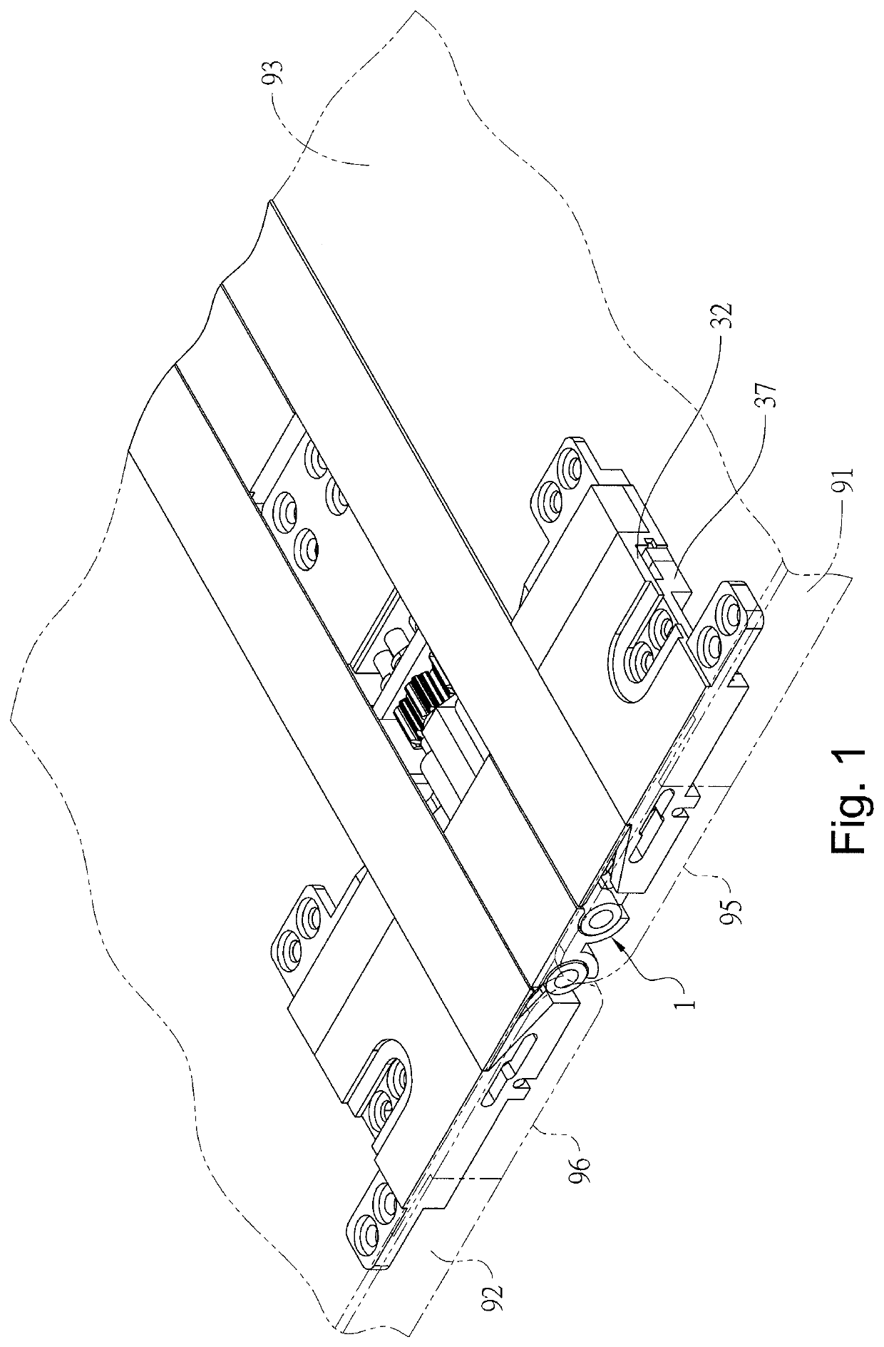
[0035]Referring to FIG. 1, one end surface of the hinge module 1 for a foldable type device of the present invention is simultaneously connected to two halves of a flexible display 93, and another end surface of the hinge module 1 is respectively connected to a first housing 91 and a second housing 92 so as to have the first housing 91 and the second housing 92 moved in an leakage way, and have the first housing 91 and the second housing 92 rotated in an opposite direction, so as to have the flexible display 93 folded or unfolded in an opposite direction. As shown in FIG. 8, when the device of the present invention is folded, an accommodating space 94 is formed at the intersection of the first housing 91 and the second housing 92 to accommodate the curved central part of the flexible display 93.

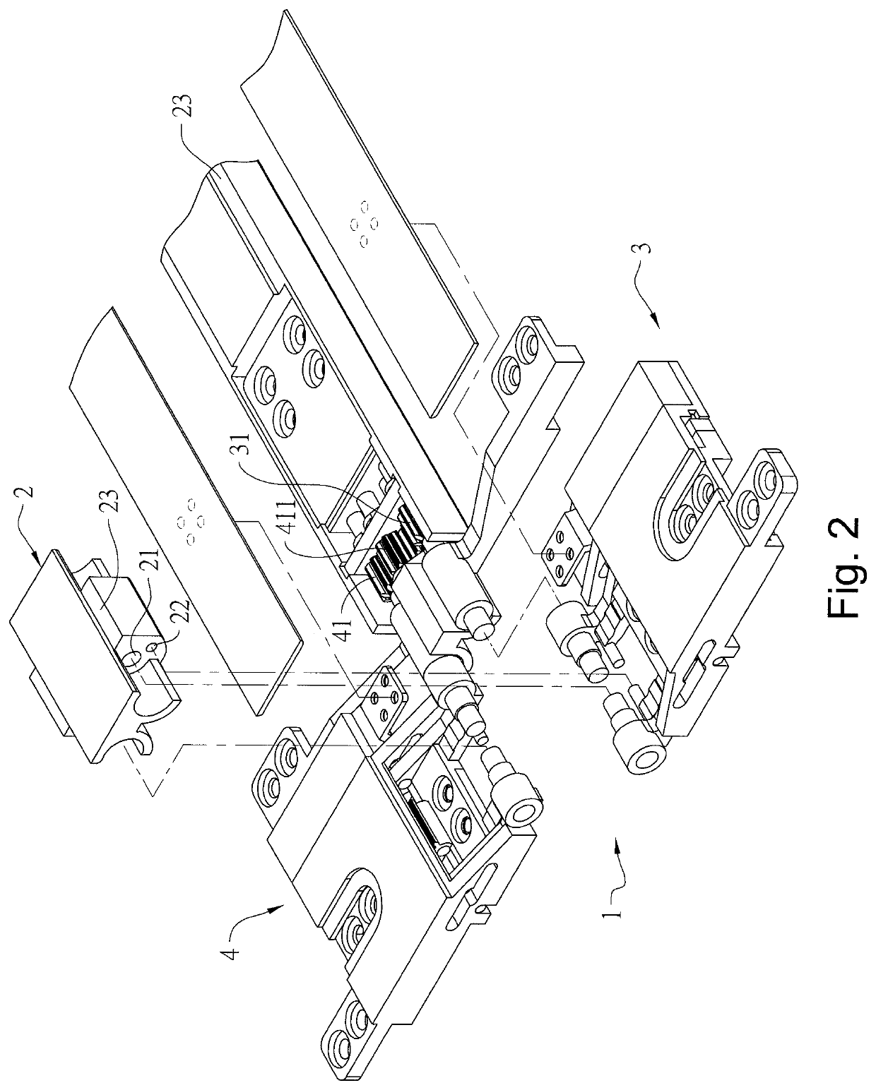
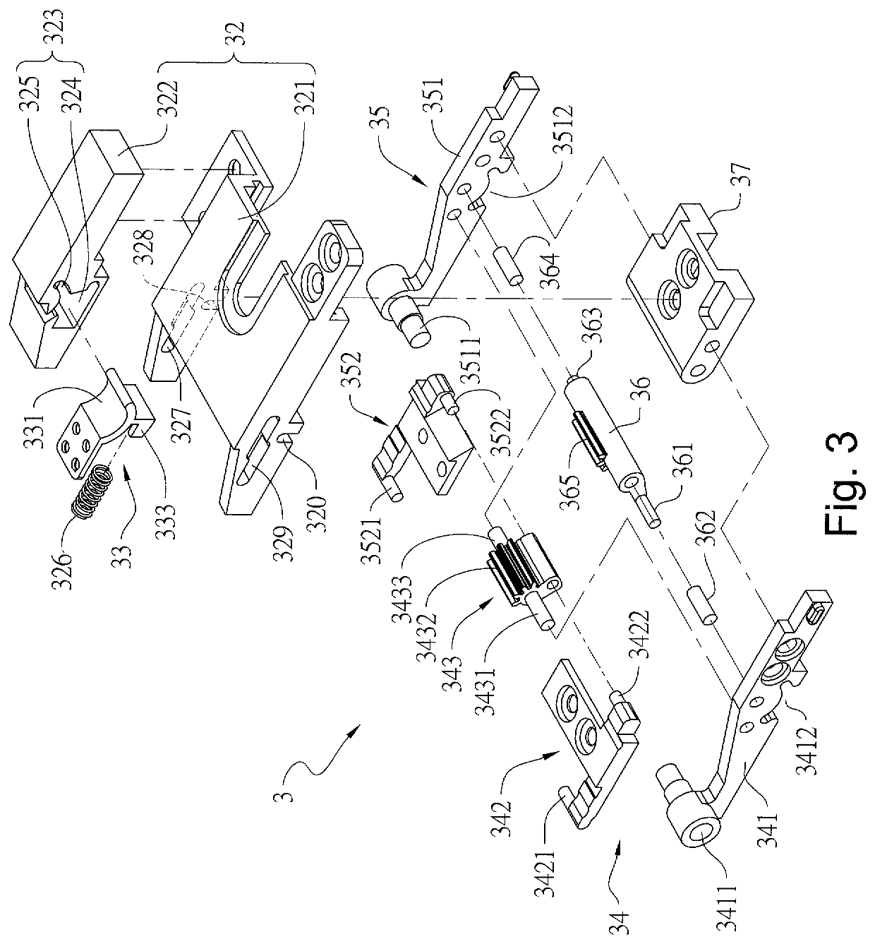
[0036]As shown in FIG. 2, the preferred embodiment of the hinge module 1 for a foldable type device of the present invention comprises a base 2, a first sliding mechanism 3 and a second slidi...


PUM


Abstract

The present invention provides a hinge module for a foldable-type device, one end surface of which is respectively connected to a first housing and a second housing, and another end surface of which is connected to a flexible display so as to have the flexible display folded when the first housing and the second housing is rotated. The hinge module comprises a base and a first sliding mechanism, wherein the base is provided between the first and second housings, and the first sliding mechanism comprises a first sliding cover, a supporting member and a left four-linkage-mechanism and a swinging member. When the first and second housings are rotated to move the left four-linkage-mechanism and the swinging member, the first sliding cover is moved in a linkage way, and one supporting portion of the supporting member is moved by an angle to accommodate the curved part of the flexible display.

Description

FIELD OF THE INVENTION[0001]The present invention relates to a hinge device, and more particularly to a hinge module for a foldable type electronic device.BACKGROUND OF THE INVENTION[0002]The conventional foldable electronic devices, such as a foldable display, mainly connects the sides of the support members of display units through a split shaft or a multi-axis shaft to form a pivoting connection, thereby making the flexible display or each display unit folded or unfolded in an opposite direction. Since the current electronic devices are mainly designed to be thinner in order to be carried by users, the spacing between two bodies that can be reserved for the hinge would become narrower and narrower, and the dimensional requirements for the hinge are bound to be reduced.[0003]For example, the Chinese Patent entitled with “A Foldable display” with No. CN105788452A has disclosed a foldable structure of a hinge, which mainly has a first body and a third body of the hinge respectively ...

Claims


Application Information

Patent Timeline
Patent Type & Authority Applications(United States)
IPC IPC(8): G06F1/16G09F9/30
CPCG09F9/301G06F1/1641G06F1/1616F16C11/04G06F1/1681
Inventor HSU, YU-TSUN
Owner JARLLYTEC CO LTD
Learn More