Antenna

Inactive Publication Date: 2005-10-04
NEC CORP
View PDF13 Cites 8 Cited by
  • Summary
  • Abstract
  • Description
  • Claims
  • Application Information

AI Technical Summary

Benefits of technology

[0008]It is therefore an object of the present invention to provide an antenna which has a plurality of helical antenna elements with improved antenna characteristics.
[0012]In the helical antenna as described above, since the connection is directly connected only to the first helical antenna, the first helical antenna element and second helical antenna element can be relatively weekly coupled to each other, so that a change in structure (a winding pitch and / or the number of turns) of one helical antenna element will not significantly affect the characteristics of the other helical antenna element. As a result, the helical antenna elements can be modified in structure independently of each other to facilitate adjustments of the characteristics of the two helical antenna elements, thereby readily providing an antenna which satisfactorily operates at two frequencies.
[0013]Preferably, in the antenna of the present invention, the first helical antenna element is fed from one end thereof, while the second helical antenna element is opened at both ends thereof. As a result, the first helical antenna element can resonate with approximately a quarter wavelength (λ / 4), while the second helical antenna element can resonate with approximately half wavelength (λ / 2). Further, according to this structure, appropriate matching can be achieved at both frequencies, so that it is possible to provide an antenna which satisfactorily operates at both frequencies even when a first resonant frequency is substantially an integer multiple of a second resonant frequency.

Problems solved by technology

Moreover, in the helical antenna illustrated in FIGS. 1A and 1B, two helical antenna elements 91, 92 are directly connected by an electric conductor, that is, they are connected through a DC (direct current) path, so that if one of the helical antenna elements is varied in structure (the winding pitch and / or number of turns) to change the antenna characteristics, this causes a change in the characteristics of the other helical antenna element, with the result that difficulties are encountered in adjusting both elements to respective optimal characteristics.
Particularly, when one frequency is substantially twice as high as the other frequency, the half wavelength resonance condition is difficult to realize at any frequency because the antenna element is powered from one end thereof.

Method used


Image

  • Antenna
  • Antenna
  • Antenna

Examples


first embodiment

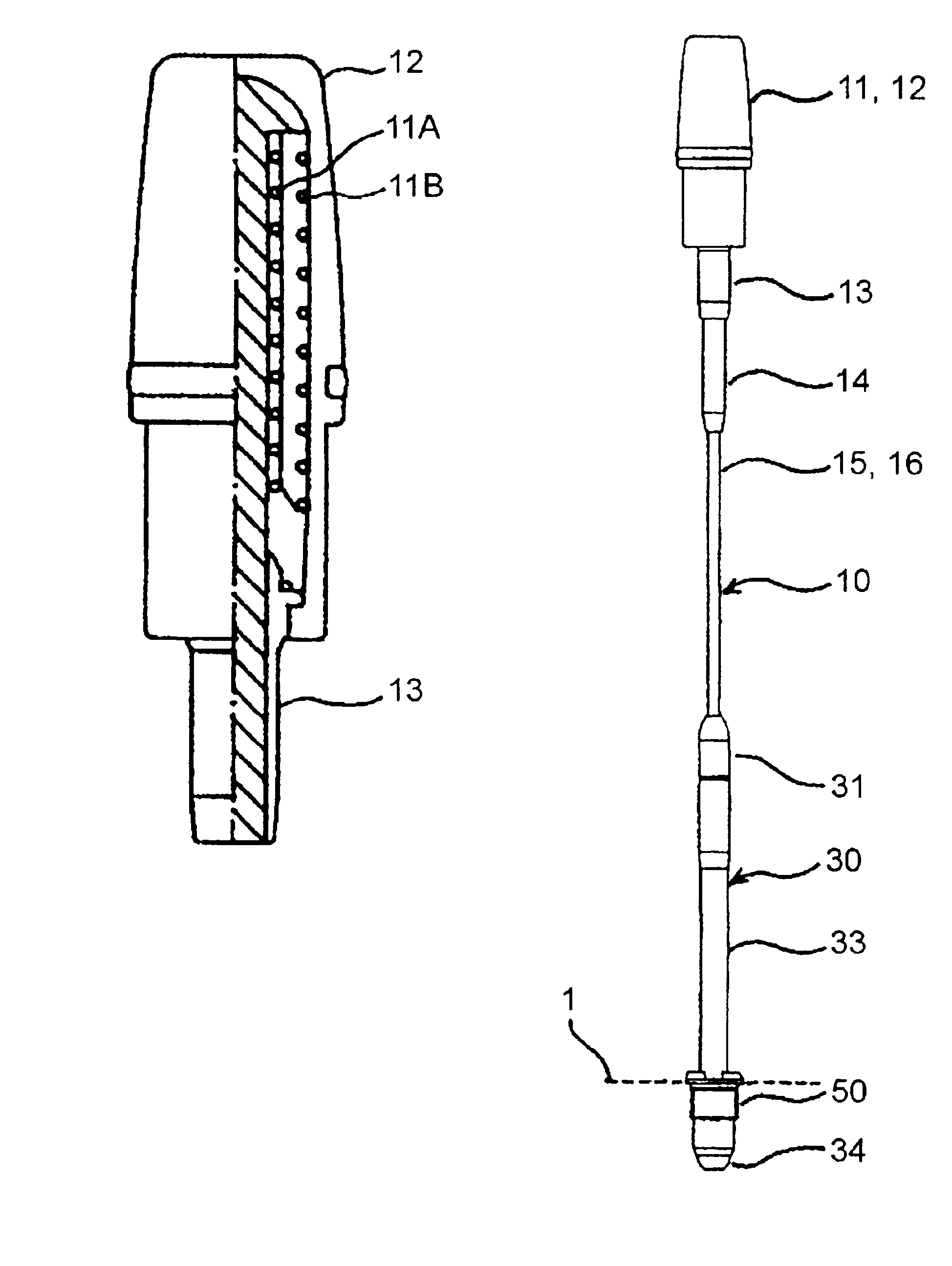
[0023]A helical antenna according to the present invention illustrated in FIG. 2 comprises first coil element 11A and second coil element 11B each of which is formed by helically winding a conductive wire. Second coil element 11B is arranged outside of first coil element 11A and coaxially with first coil element 11A. Coil elements 11A, 11B are both fabricated as helical antenna elements. Therefore, both coil elements 11A, 11B are wound at different diameters when they are formed into helical antennas. In FIG. 2, a portion to the left of a one-dot chain line shows an outer appearance of the helical antenna, while a portion to the right of the one-dot chain line shows a cross-sectional view of the same.

[0024]In the illustrated helical antenna, first coil element 11A has an electric length to resonate at first resonant frequency (fL) with one end thereof functioning as a feeding point. Second coil element 11B is open at both ends, and has an electric length to resonate at second resona...

second embodiment

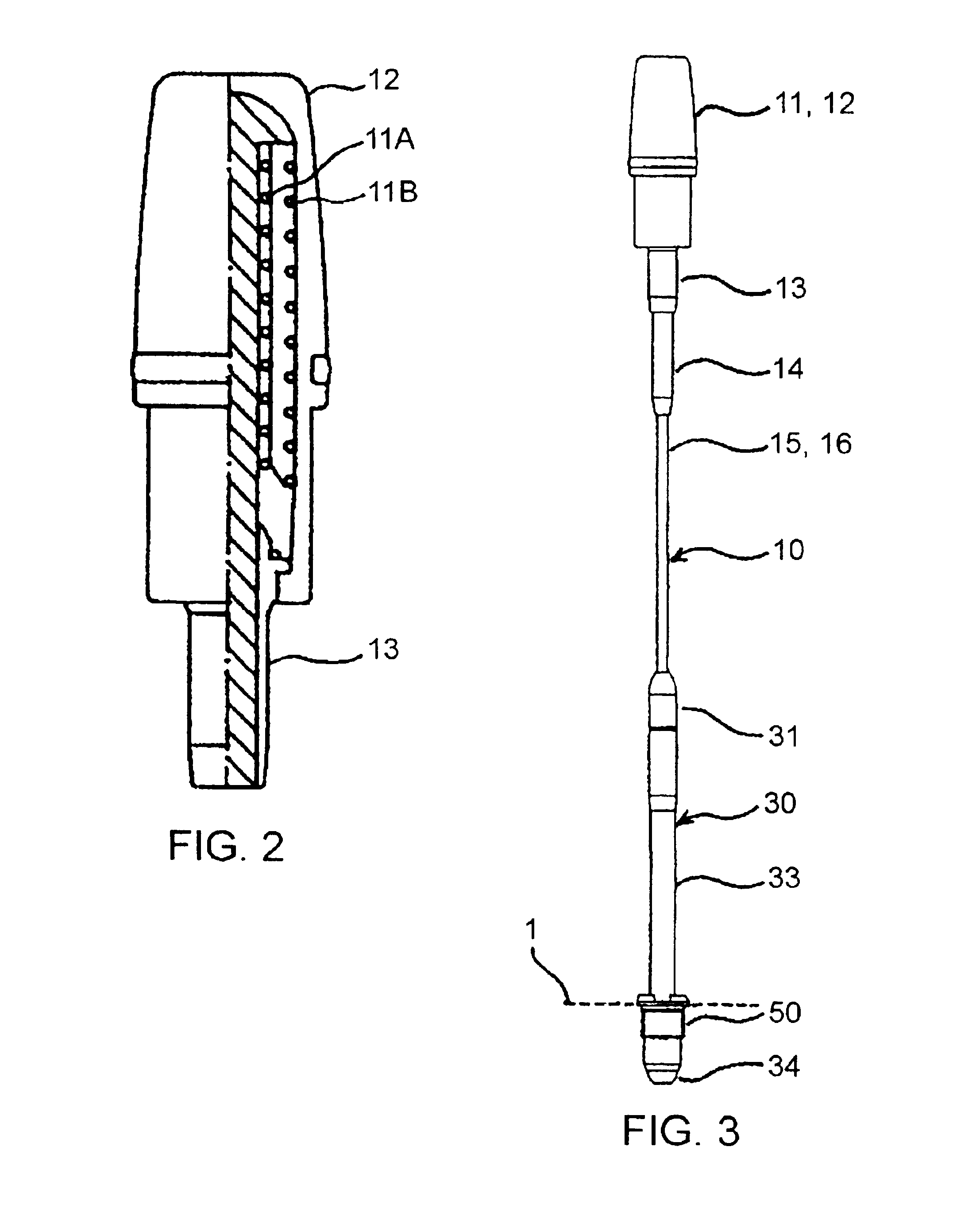
[0035]Next, description will be made on a whip antenna according to the present invention.

[0036]The whip antenna according to the second embodiment illustrated in FIG. 3 is a telescopical whip antenna which has a rod antenna disposed below the helical antenna in the aforementioned first embodiment. Specifically, this whip antenna is a so-called two-stage telescopical whip antenna which is made up of upper element 10, and lower element 30 disposed below upper element 10. Upper element 10 is electrically and mechanically connected to lower element 30 through a joint metal fixture 31 fixed at a leading end of lower element 30, and upper element 10 can be retracted into lower element 30. A helical antenna (i.e., coil element 11) is further disposed at a leading end of upper element 10. The aforementioned helical antenna in the first embodiment is used as this helical antenna.

[0037]First, upper element 10 and coil element 11 will be described. Upper element 10 mainly comprises rod conduc...


PUM


Abstract

A helical antenna capable of operating at a plurality of different resonant frequencies. The helical antenna has a first helical antenna element, a second helical antenna element arranged coaxially with the first helical antenna element and coupled to the first helical antenna element through capacitive coupling, and a metal connection directly connected only to the first helical antenna element to fed the helical antenna. The first helical antenna element is fed through one end thereof to function as a quarter-wave antenna. The second helical antenna element is fed through capacitive coupling to function as a half-wave antenna.

Description

BACKGROUND OF THE INVENTION[0001]1. Field of the Invention[0002]The present invention relates to an antenna suitable for use in a portable radio device and the like, and more particularly, to an antenna which resonates at a plurality of frequencies.[0003]2. Description of the Related Art[0004]A portable radio device represented by a portable telephone device or a cellular telephone device has an antenna mounted on the top of its housing, to radiate or capture radio waves through the antenna for transmission and reception operations. A portable telephone is provided with an antenna which is made up of an upper helical antenna and a lower whip antenna (or rod antenna). The antenna is arranged telescopically to and from a housing, such that a gain is increased when the antenna is extended, while the antenna protrudes less from the housing when it is retracted. Also, some recent portable telephones support a plurality of radio communication systems, and an antenna used in such a portabl...

Claims


Application Information

Patent Timeline
IPC IPC(8): H01Q5/00H01Q11/08H01Q1/24H01Q11/00H01Q5/10H01Q5/378H01Q5/40H01Q9/32
CPCH01Q1/242H01Q1/244H01Q5/47H01Q5/378H01Q5/40H01Q11/08
Inventor SAITO, TETSUYAHIRAKU, SUMIO
Owner NEC CORP
Why Eureka
Try Eureka