Small antenna and a multiband antenna

a multi-band antenna and small antenna technology, applied in the direction of resonant antennas, antenna earthings, protective materials radiating elements, etc., can solve the problems of difficult miniaturization of handheld devices, deterioration of antenna characteristics, and inability to use handheld devices with incorporated antennas, etc., to achieve low cost manufacturing

Inactive Publication Date: 2005-05-05
FURUKAWA ELECTRIC CO LTD
View PDF4 Cites 9 Cited by
  • Summary
  • Abstract
  • Description
  • Claims
  • Application Information

AI Technical Summary

Benefits of technology

[0008] It is an object of the present invention to constitute an antenna with a small size and wide band by combining linear conductor elements, and provide a small antenna which is resistant to effects of a hand, etc. to ensure excellent antenna characteristics even when the antenna is incorporated into a handheld device, and is suitable for miniaturization.
[0009] It is another object of the present invention to provide a multiband antenna which enables easy adjustment of resonance frequencies to prescribed frequencies and ensures excellent antenna characteristics for each resonance frequency when the antenna is shared by a plurality of frequencies, is suitable for reduction in antenna size, and enables reduction in manufacturing cost.

Problems solved by technology

Therefore, the miniaturization of the handheld devices is difficult.
Therefore, the wire antenna shown in FIG. 16 needs wasteful spaces in the upper portion on the circuit board 102, and though the antenna itself is miniaturized, it is not suitable for use in an incorporated antenna in a handheld device.
Accordingly, when such an antenna is incorporated into a handheld device, holding the handheld device by hand directly affects the antenna, and antenna characteristics may deteriorate.
Further, when either the conventional planar antenna or wire antenna is used to constitute a multiband antenna allowing the use of a plurality of frequencies, the antenna size is large, it is difficult to adjust resonance frequencies to prescribed frequencies respectively, and it is difficult to ensure excellent antenna characteristics for all of the plurality of frequencies.

Method used


Image

  • Small antenna and a multiband antenna
  • Small antenna and a multiband antenna
  • Small antenna and a multiband antenna

Examples


first embodiment

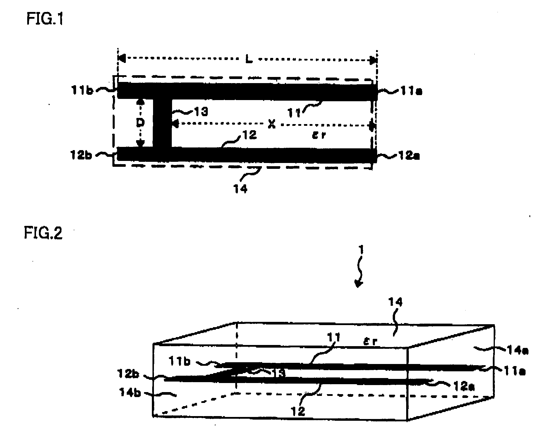
[0052] As shown in FIG. 1, the small antenna 1 has a structure where an antenna pattern is configured that combines a fed line element 11, a grounded line element 12 and a shorting element 13, and contained in a dielectric 14.

[0053] The fed line element 11 is formed of a conductor pattern having an outer shape with a longitudinal length from one end 11a to the other end 11b and with a predetermined width, where the end 11a is connected to a feeding point, while the end 11b is opened. The grounded line element 12 is formed of a conductor pattern having an outer shape with a longitudinal length from one end 12a to the other end 12b and with a predetermined width, where the end 12a is connected to a ground terminal, while the end 12b is opened. The fed line element 11 and grounded line element 12 are the same as each other in the direction from the end 11a, 12a to the end 11b, 12b, respectively, and are arranged in parallel with a gap D.

[0054] In addition, in the example as shown in ...

second embodiment

[0082] A specific design example of the triple-band antenna 2 will be described below. Table 2 shows design conditions of the triple-band antenna 2 on the assumption that the antenna is applied to a cellular phone with three functions, CDMA, GPS and PCS, and thus used for three frequencies, 900 Mz-band (CDMA), 1.575 GHz-band (GSP) and 1.8 GHz-band (PCS).

TABLE 2ItemDesign conditionLength L1 of each line element on the first layer20mmLength L2 of each line element on the second layer15mmLength L3 of each line element on the third layer20mmGap D between the fed line element and grounded1mmline elementSpace between layers1mmWidth of each element1mmSpace between each line element on the third layer0.5mmand ground pattern of the circuit boardRelative permittivity εr of the dielectric8

[0083] According to the design conditions as shown in Table 2, a specific shape and arrangement of the triple-band antenna 2 were set corresponding to the structure as shown in FIGS. 8 to 11. FIG. 13 is a si...


PUM


Abstract

A small antenna comprising: an antenna pattern consisting of: two linear conductor elements; a shorting element that electrically connects the two linear conductor elements and a dielectric in a predetermined shape that contains the antenna pattern therein; where the two linear conductor elements are arranged in parallel with each other, and one of the two linear conductor elements is used as a fed line element, while the other is used as a grounded line element.

Description

BACKGROUND OF THE INVENTION [0001] 1. Field of the Invention [0002] The present invention relates to technical fields of small antennas and multiband antennas capable of being incorporated into a handheld device. [0003] 2. Related Art [0004] In recent years, handheld devices such as cellular phones have become widespread, and demands are strong for miniaturization of the handheld devices. In particular, miniaturization of an antenna utilized by a handheld device is required, and techniques become important for providing a small antenna capable of being integrated into a handheld device. Although a planar antenna can be adopted as an antenna for a handheld device, a bandwidth strongly depends on the antenna size, and the size of the planar antenna is increased to support a wide band. Therefore, the miniaturization of the handheld devices is difficult. Accordingly, a wire antenna comprised of a linear conductor is generally adopted as an antenna for a handheld device. For example, as ...

Claims


Application Information

Patent Timeline
Patent Type & Authority Applications(United States)
IPC IPC(8): H01Q21/30H01Q1/24H01Q1/36H01Q1/38H01Q1/40H01Q1/48H01Q5/10H01Q5/357H01Q9/04H01Q9/30H01Q13/08
CPCH01Q1/243H01Q5/357H01Q9/30H01Q1/36H01Q1/38
Inventor TAMAOKA, HIROYUKI
Owner FURUKAWA ELECTRIC CO LTD
Why Eureka
Try Eureka