Portable wireless device

A wireless device and portable technology, applied in the field of portable wireless devices, can solve problems such as difficulties and inability to obtain antenna characteristics, and achieve the effect of good antenna characteristics

Inactive Publication Date: 2010-12-08
SHARP KK
View PDF1 Cites 8 Cited by
  • Summary
  • Abstract
  • Description
  • Claims
  • Application Information

AI Technical Summary

Problems solved by technology

[0003] There are some difficulties in obtaining good antenna characteristics over wideband or multiple frequency bands with a portable wireless device as described above
In particular, in the case of a foldable portable wireless device comprising two cases (i.e., an upper case and a lower case), it is sometimes not possible to obtain good frequency bands on all used frequency bands with only a single connection between the upper and lower cases. Antenna Characteristics

Method used


Image

  • Portable wireless device
  • Portable wireless device
  • Portable wireless device

Examples


no. 1 example

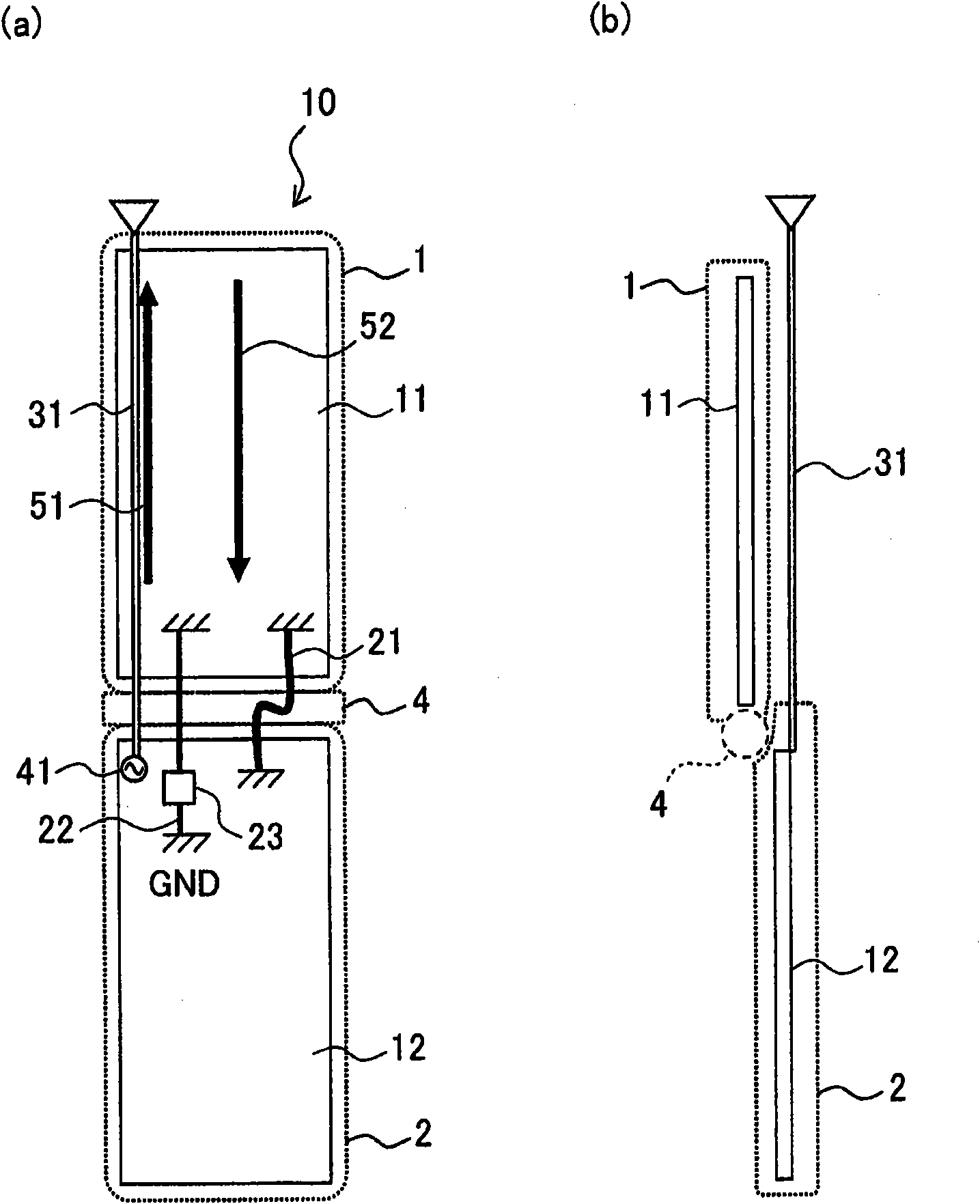
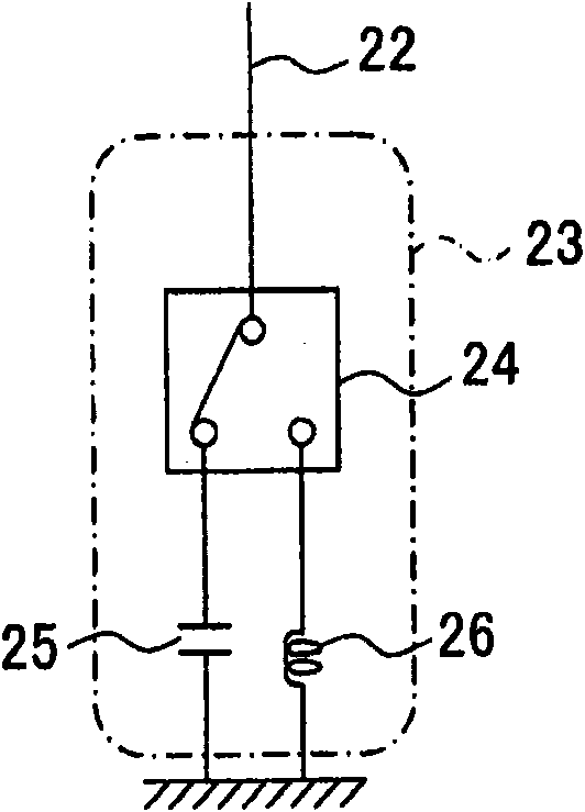
[0052] Various embodiments of the present invention are described below with reference to the accompanying drawings. figure 1 A diagram showing a configuration example of a portable wireless device according to a first embodiment of the present invention, in which figure 1 (a) is a front view and figure 1 (b) is a side view. Such as figure 1 As shown in (a) and (b), the portable wireless device 10 according to the present embodiment connects the first circuit member 11 and the second circuit member 12 using a thin coaxial cable 21 including a A signal line that transmits electrical signals of the first circuit member 11 and the second circuit member 12 placed in the first housing 1 and the second housing 2, respectively. Furthermore, the first circuit member 11 and the second circuit member 12 are connected with a connection element 22 including a conductive pattern or the like on a metal sheet or a substrate via a reactance-switchable reactance element 23 . A freely exten...

no. 2 example

[0079] A second embodiment of the present invention is described below with reference to the drawings. Figure 4 A configuration is shown in which the second antenna 32 and the third antenna 33 have been added near the hinge portion 4 of the portable wireless device 10 according to the first embodiment. figure 1 Similar components found in are assigned the same reference numerals, and descriptions thereof are omitted.

[0080] In which the frequency band used for the whip antenna 31 is the UHF frequency band, the W-CDMA (Wideband Code Division Multiple Access: 830-885 MHz) frequency band in the 800 MHz frequency band for the second antenna 32, and the 2 GHz frequency band for the third antenna 33 The case of the W-CDMA (1920-2170MHz) frequency band is given as an example to describe,

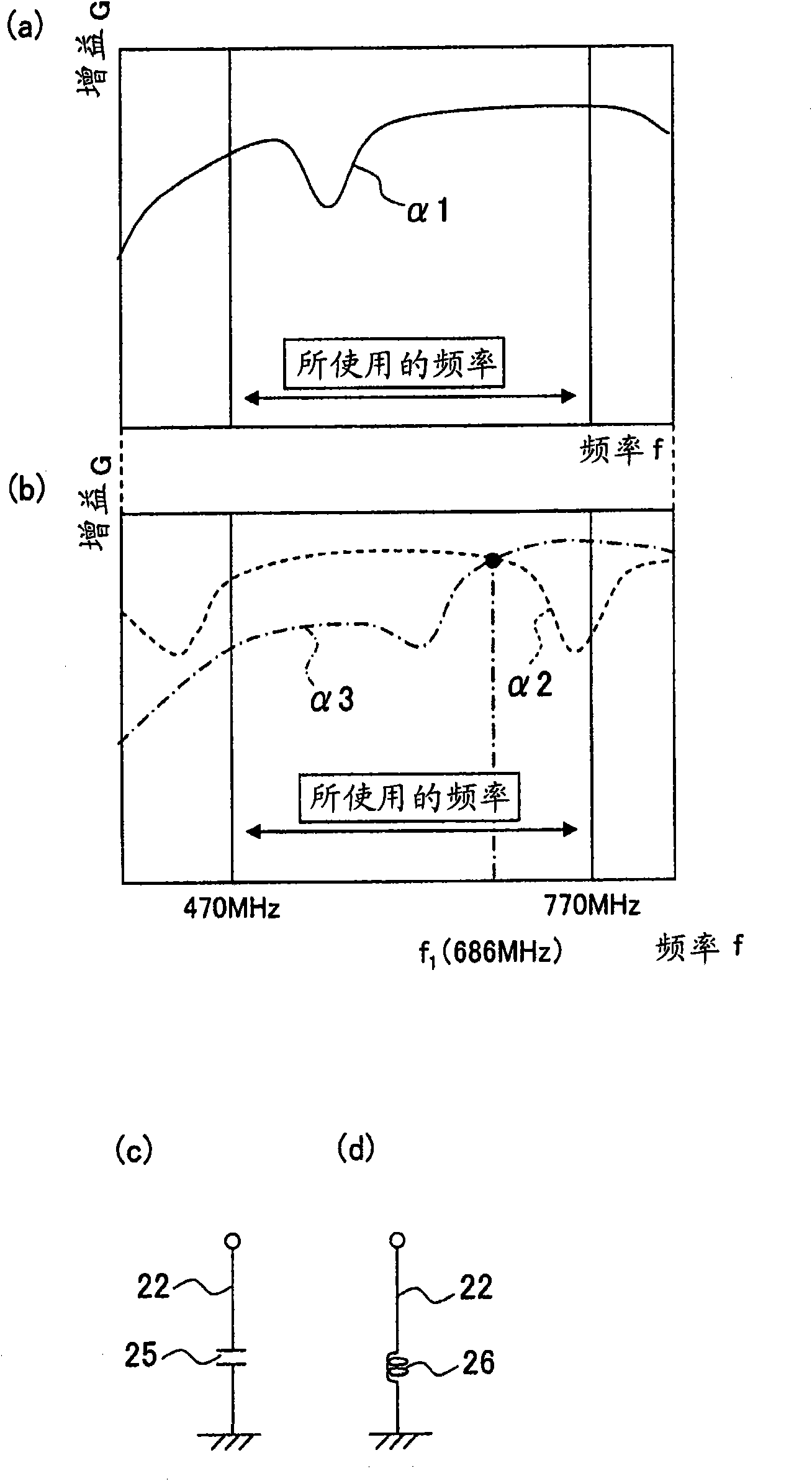
[0081] By configuring the whip antenna 31 (the frequency band used is the UHF band) as in the first embodiment, the whip antenna 31 can obtain good antenna characteristics.

[0082] When the w...

no. 3 example

[0093] A third embodiment of the present invention will be described below with reference to the drawings. Such as Figure 6AAs shown in (a) to (c), the portable wireless device 100 according to the present embodiment includes: a first circuit member 111 and a second circuit member 112 inside the first casing 101 and the second casing 102, the first A housing 101 and a second housing 102 are openably / closably joined by a third housing 103 including a hinge portion 104; and a hinge portion 104 at the second housing 102 The first, second and third antennas 131, 132 and 133, wherein the first circuit member 111 and the second circuit member 112 are connected by a thin coaxial cable 121, the thin coaxial cable 121 includes a , the signal line passing through the inside of the third casing 103 . In addition, the third housing 103 including the hinge portion 104 includes a conductive member. The third housing 103 and the second circuit member 112 are connected via a reactance swi...


PUM


Abstract

In a portable wireless device (100), a thin coaxial cable (121) connects electrical signals, which are transmitted from first and second circuit members (111, 112) stored in first and second casings (101, 102). The casings are connected to be opened and closed by a third casing (103) which has a hinge section (104). The first and second circuit members (111, 112) are connected to each other by a connecting element (122) with a reactance element (123) arranged in between for switching reactance. The device is provided with first, second and third antennas (131, 132, 133) in the vicinity of the hinge section (104) of the second housing (102). Even if the first casing (101) rotates substantially 90 degrees within the same flat surface, excellent antenna characteristics can be obtained with a discretionary frequency by switching connection impedance of the first and second casings (101, 102), corresponding to frequencies used in terminal states, respectively.Thus, the casings are connected in the ideal manner by switching the connection impedance with a discretionary frequency between the casings, and excellent antenna characteristics are obtained with a discretionary frequency for each discretionary state.

Description

technical field [0001] The present invention relates to a portable wireless device, and more particularly, to a portable wireless device capable of achieving good antenna characteristics at a given frequency for each state of a terminal. Background technique [0002] Recently, for portable wireless devices, there has been an increasing demand for not only call and e-mail functions but also various communication services such as television broadcast reception functions, Internet connection functions, and the like. In order to meet such demands while achieving high-quality communication, it is common to equip portable wireless devices with one antenna having broadband antenna characteristics or with multiple antennas. In addition, portable wireless devices that enhance convenience by making it possible to change their shape according to used communication services or contents are also frequently found. [0003] There are some difficulties in obtaining good antenna characteris...

Claims


Application Information

Patent Timeline
Patent Type & Authority Applications(China)
IPC IPC(8): H01Q1/48H01Q1/24H01Q3/44H04B1/38H04M1/02H04B1/3822H04B1/40
CPCH01Q1/244H04M1/0208H01Q1/48H04B1/18H04M1/0233H04B1/0458H01Q3/44
Inventor 近藤俊范武部裕幸
Owner SHARP KK
Why Eureka
Try Eureka