Self-levelling foot arrangement for an appliance

a self-leveling and laundry appliance technology, applied in the field of laundry appliances, can solve the problems of significant ergonomic disadvantage of the top-loading laundry appliance of the prior art clothes dryer

Inactive Publication Date: 2007-07-31
FISHER & PAYKEL APPLIANCES LTD
View PDF60 Cites 35 Cited by
  • Summary
  • Abstract
  • Description
  • Claims
  • Application Information

AI Technical Summary

Benefits of technology

[0020]It is an object of the present invention to provide a laundry drying appliance and or associated parts and or associated methods which at least go some way towards overcoming disadvantages of the prior art or which will at least provide the public with the useful choice.

Problems solved by technology

The prior art clothes dryer has a significant ergonomic disadvantage to a top loading laundry appliance.
It is a particular disadvantage when washing has to be transferred from a top loading clothes washing machine to a front loading clothes dryer.

Method used


Image

  • Self-levelling foot arrangement for an appliance
  • Self-levelling foot arrangement for an appliance
  • Self-levelling foot arrangement for an appliance

Examples


Embodiment Construction

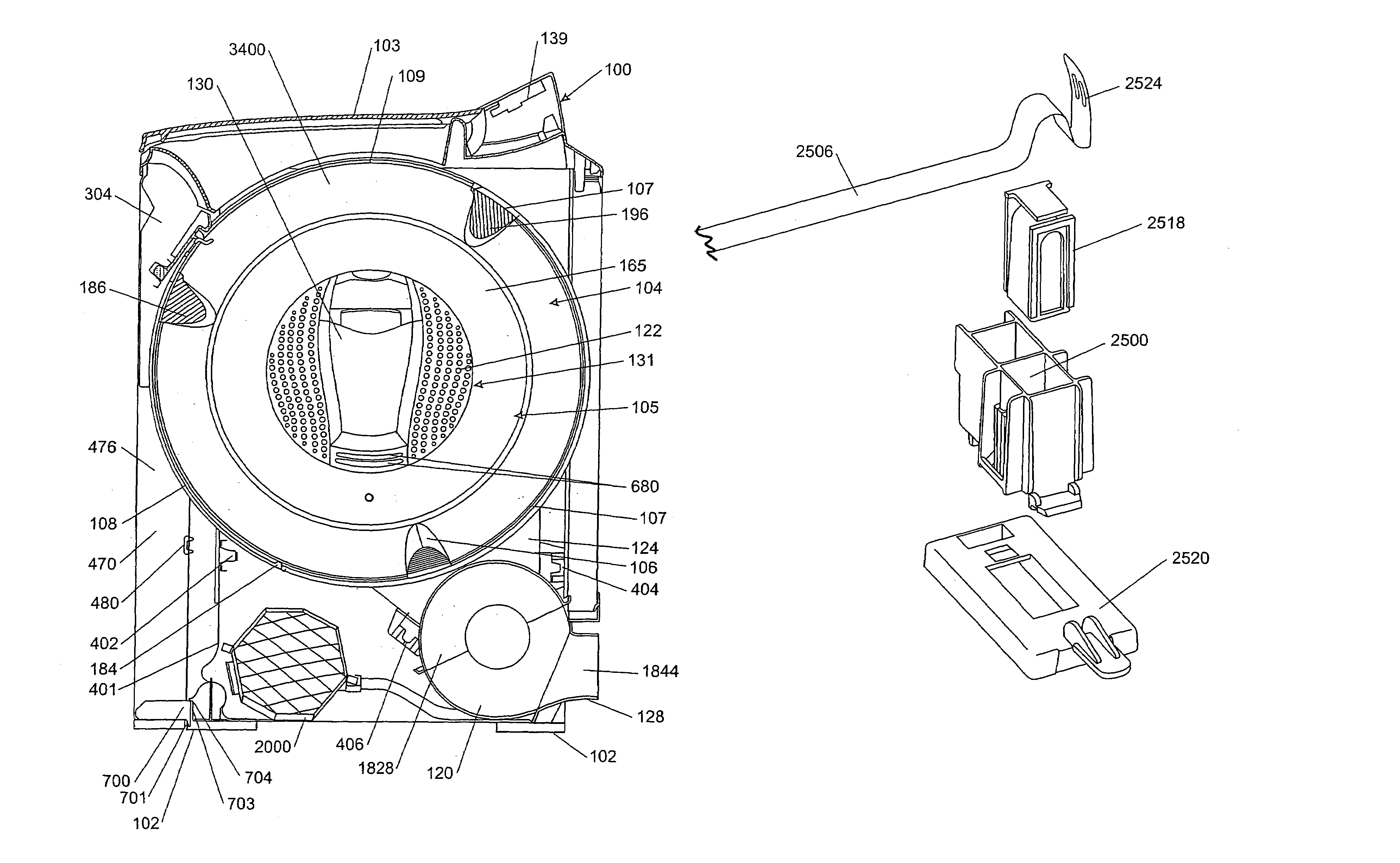
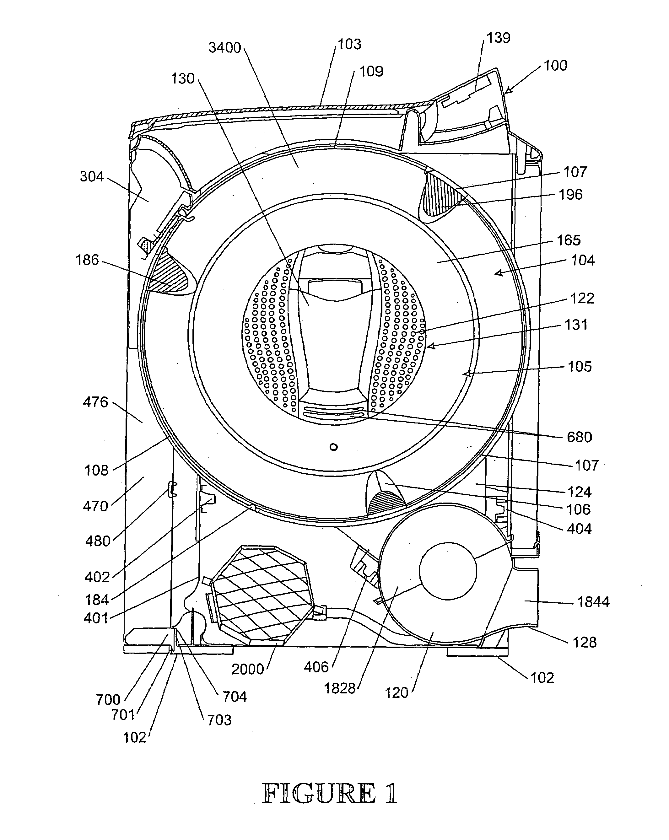
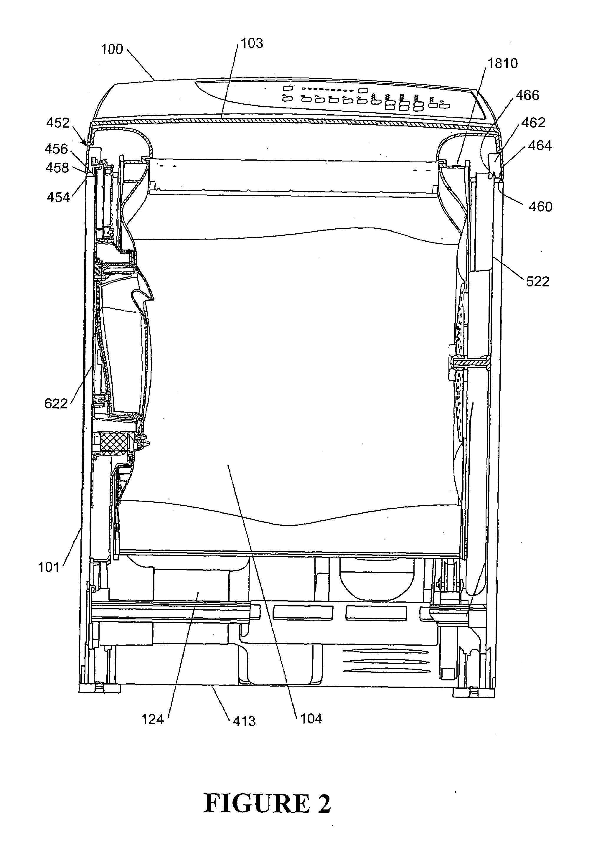
[0082]Referring to FIGS. 1 and 2, clothes dryer100 includes a cabinet 101 with a top mounted hinging lid 103. The cabinet 101 includes four side walls and a floor. Feet 102 are provided on the lower surface of the cabinet 101 to support the cabinet on a supporting surface (eg: floor). A cylindrical drum 104 is supported horizontally within the cabinet 101. The drum 104 includes a sliding hatch opening in its circumferential skin. The cabinet 101 includes a contoured opening below the lid 103 to in use allow access to the sliding opening of the drum 104.

[0083]The drum 104 is supported horizontally within the cabinet 101 from its ends 105 and 110. Each drum end is supported on a chassis. In the preferred form, and in accordance with one of the inventions herein, the chassis is moved forward from the cabinet 101 with the front of the cabinet removed. In the preferred form described and illustrated movement of the chassis from the cabinet, together with the drum and other mechanical ass...


PUM


Abstract

A self adjusting foot arrangement for an appliance cabinet has a first socket connected with the cabinet and a second socket connected with the cabinet spaced apart from the first socket. A foot downwardly protrudes from each socket and is moveable along axis into and out of the respective socket. A non-extensile band is fixed at one end to the first socket, passes into the first socket to bear on the first foot and is fixed at its other end to the second socket passing into the second socket to bear on the second foot. The band passes over the top of each foot within the respective socket.

Description

[0001]This application is a divisional application of PCT / NZ03 / 00065, entitled “A Laundry Appliance” which has an international filing date of Apr. 10, 2003, which was published in English on Oct. 23, 2003 under International Publication Number WO 03 / 087459.BACKGROUND TO THE INVENTION[0002]1. Field of the Invention[0003]The present invention relates to laundry appliances and in particular consumer laundry appliances for the drying of damp textile articles, such as items of clothing, towels and bed linen.[0004]2. Summary of the Prior Art[0005]Prior art clothes drying machines are generally of a type having a rotatable metal drum supported within a rectangular cabinet. The rotatable drum includes an open end facing the front of the cabinet and a substantially closed end at the rear of the cabinet. Access is gained to the open end of the drum by opening a door or hatch on the front face of the cabinet.[0006]The prior art clothes dryer has a significant ergonomic disadvantage to a top l...

Claims


Application Information

Patent Timeline
Patent Type & Authority Patents(United States)
IPC IPC(8): F16M11/26D06F39/12D06F58/04D06F58/08D06F58/20F16M11/24
CPCD06F39/125D06F58/04D06F58/08D06F58/20D06F34/08D06F2103/46D06F2105/46
Inventor GUINIBERT, ALLEN JAMESJACKSON, RUSSELL JOSEPHJOHNSON, HUGH GRIFFITHPITT, DANIEL KEITH RAPHAELMCGREGOR, BRUCE REGINALD FRANKFRAZERHURST, GEOFFREY SIMON
Owner FISHER & PAYKEL APPLIANCES LTD
Why Eureka
Try Eureka