Bearing device with sensor and rolling bearing with sensor

a technology of sensor and bearing, applied in the direction of mechanical equipment, devices using electric/magnetic means, instruments, etc., can solve the problems of low productivity, difficult force and fixing respective members, and error in sensor output 640, so as to prevent grease in the bearing space, increase the accuracy of pulse measurement, and reduce cost

Active Publication Date: 2007-07-31
NSK LTD
View PDF11 Cites 37 Cited by
  • Summary
  • Abstract
  • Description
  • Claims
  • Application Information

AI Technical Summary

Benefits of technology

[0060]In accordance with the sensor-bearing apparatus mentioned in the above (1), if the projection provided in the sensor cover contacts the interior of the cutout of the presser member while the rolling bearing rotates, the movement in the rotating direction is checked. Then, in company with the rotation of rotary-side bearing ring of the rolling bearing, the rotation of the sensor cover and the rotary-side bearing ring integral with the sensor cover can be checked. Accordingly, by the above sensor-bearing apparatus, even if the stationary-side bearing ring of the rolling bearing is generated with the rotating force, it is possible to exactly check the rotation of the stationary-side bearing ring, and the productivity is not reduced because the structure is simple.
[0083]In accordance with the sensor-rolling bearing mentioned in the above (20), even in case the seal is not especially equipped in the bearing space between the rotary rings, the grease in the bearing space can be prevented from flowing out outside from the bearing. Further, by making the magnet attaching member of a magnetic member, if an intensively magnetic field generating part exists around the environment, the leakage magnetic flux from the rolling elements can be avoided from going toward the magnetically sensitive elements such as the magnet or the hole IC. As a result, there is no miss-count of the speed pulse owing to erroneous action of the magnetically sensitive element, so that the pulse measuring accuracy can be heightened. Besides, since the magnet attaching member can be used as the shielding member of the magnetic flux, other parts are unnecessary, enabling to cost down.

Problems solved by technology

However, the above mentioned conventional sensor-bearing apparatus 600 is complicated in a structure of securing the whirl-stop members 606a and the sensor cover 607, so that the productivity is low.
Then, an error in output of the sensor 640 is probably caused by the circumferential dislocation.
However, depending on the resin insertion, since a complicated process is required, there is a room for making improvement with respect to production process and cost-up, accordingly.
But since a face to be processed of the step portion can not be subjected to a centerless machining, sizes are largely dispersed, and it is difficult to force and fix respective members.
Therefore, by disposing locations, an external magnetic field caused by an external noise disturbs a magnetic field formed by the member to be detected, so that such probability might be caused that the sensor cannot exactly detect the magnetic field formed by the member to be detected.
As a result, the above mentioned magnetic sensor 860 has a limitation in shortening the length in the axial direction of the sensor-bearing 850, and cannot satisfy a requirement for saving a space requested for using the sensor-bearing to many kinds of devices, including speed detection of automobiles.
Besides, an installing space is required to restrain reduction in size.

Method used


Image

  • Bearing device with sensor and rolling bearing with sensor
  • Bearing device with sensor and rolling bearing with sensor
  • Bearing device with sensor and rolling bearing with sensor

Examples


first embodiment

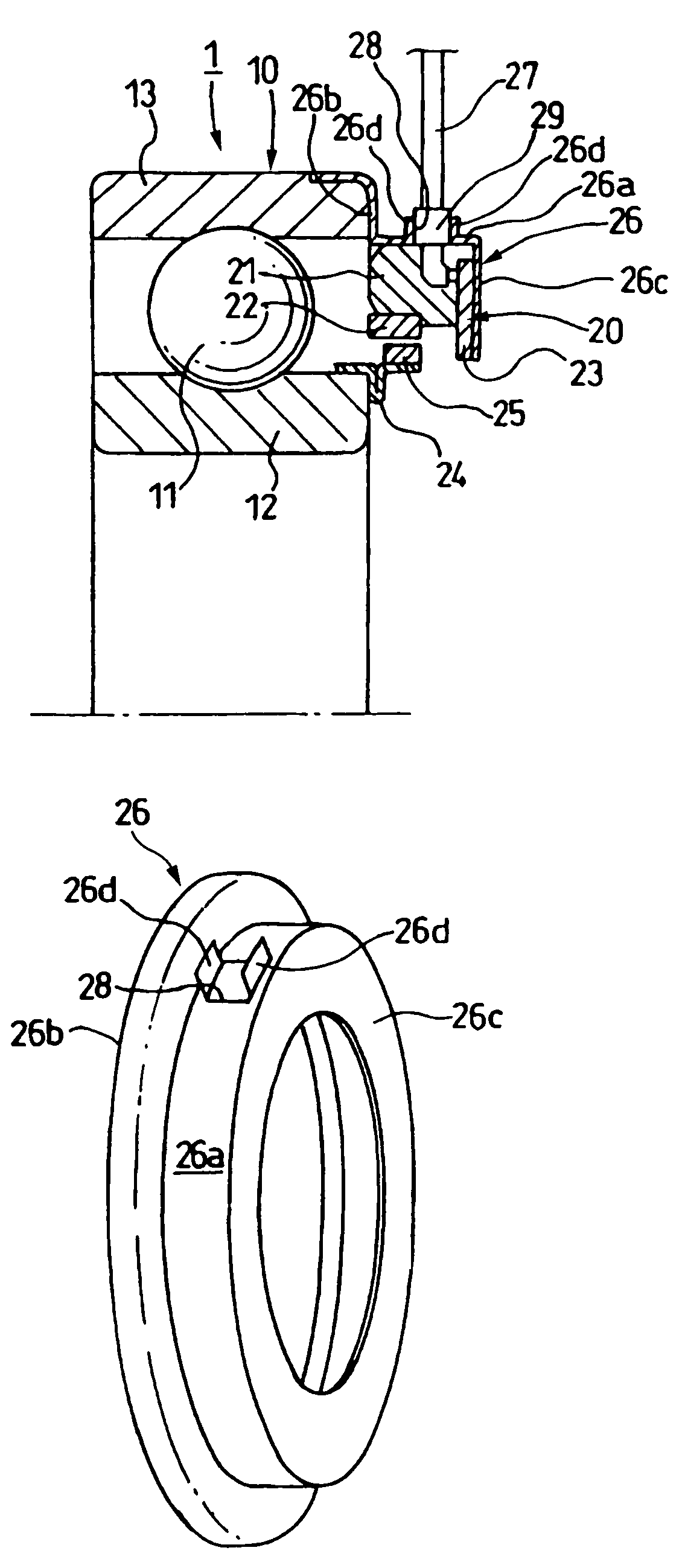
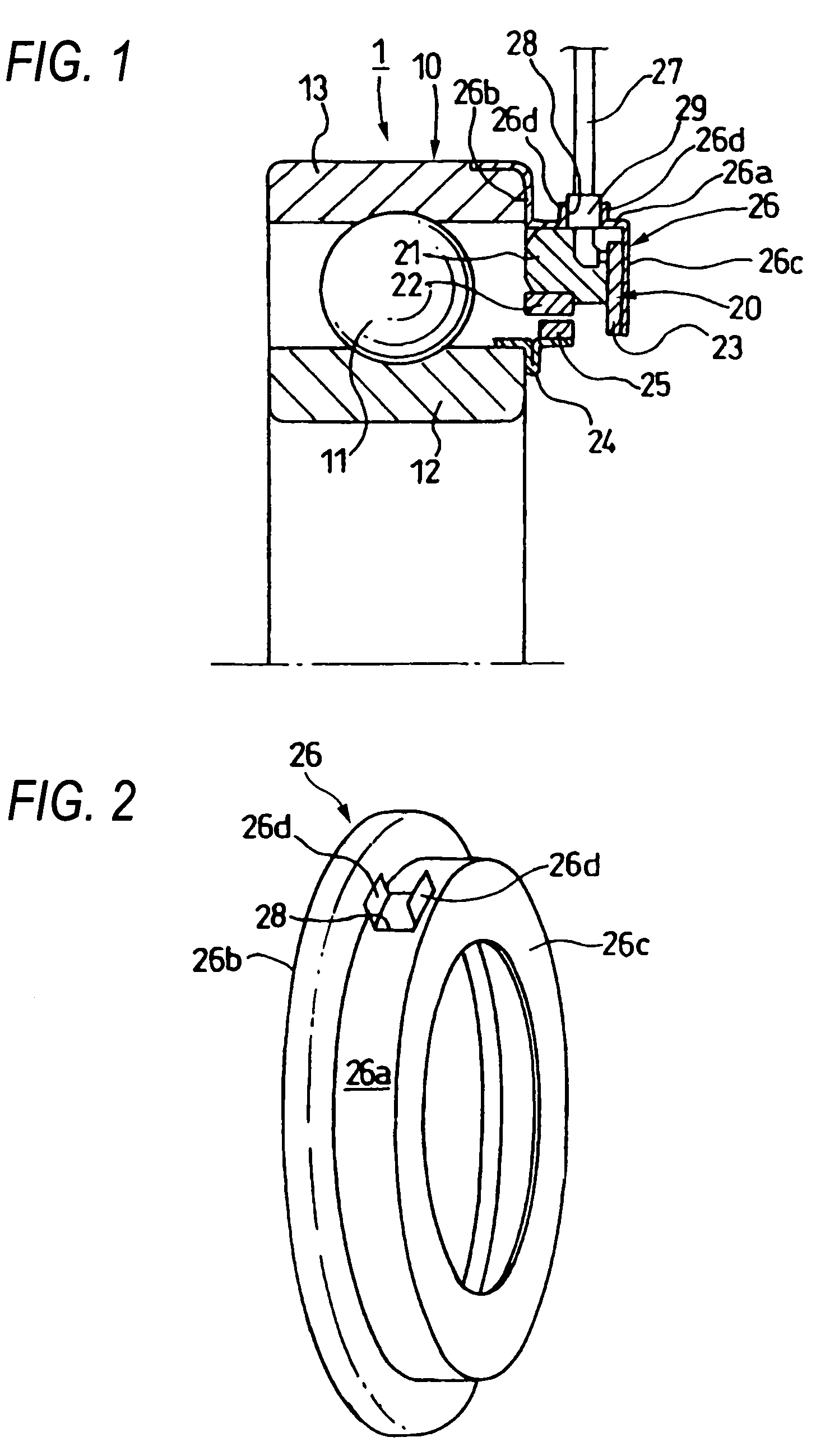
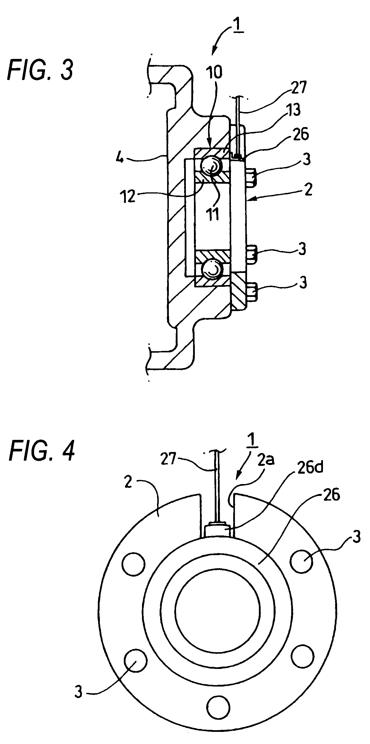
[0118]FIG. 1 is the cross sectional view of the element parts, showing the first embodiment of the sensor-bearing apparatus depending on the invention. FIG. 2 is the perspective view showing the sensor cover of the sensor-bearing apparatus of FIG. 1. FIG. 3 is the cross sectional view of the element parts showing the sensor-bearing apparatus having the rolling bearing of FIG. 1 secured to the bearing housing. FIG. 4 is a right side view of FIG. 3. FIG. 5 is a view showing the presser member of the sensor-bearing apparatus of FIG. 3.

[0119]As showing in FIG. 1, the sensor-bearing apparatus 1 is furnished with the rolling bearing 10. The rolling bearing 10 has the inner ring 12 as the rotary-side bearing ring, the outer ring 13 as the stationary-side bearing ring, and a plurality of rolling elements 11 rotatably interposed between the inner ring 12 and the outer ring 13. The plural rolling elements 11 are held by a holder (not shown) to be equidistant in a circumferential direction.

[01...

second embodiment

[0138]FIG. 6 is the perspective view for explaining the second embodiment of the sensor-bearing apparatus according to the invention. Incidentally, in the embodiments to be explained under, as to members having equivalent structures or works to those of the members already referred to, explanations will be simplified or omitted by giving the same or corresponding numerals or marks.

[0139]In this embodiment, the projection 31 of the sensor cover 30 is structured to be a single-leafed hinged door by so bending a cutout part formed in a part of the sensor cover 30 as to project in the diameter direction.

[0140]Other structures and works are the same as those of the first embodiment.

third embodiment

[0141]FIG. 7 is the perspective view showing the sensor cover of the rolling bearing of the sensor-bearing apparatus as the third embodiment of the invention.

[0142]In this embodiment, the projection 41 of the sensor cover 40 is structured to be a single-leafed hinged door by so bending the cutout part formed in a part of the sensor cover 40 as to project in the diameter direction, in opposition to the second embodiment in the axial direction (the side face 40c).

[0143]Other structures and works are the same as those of the first embodiment.


PUM


Abstract

The present invention relates to a bearing apparatus with a sensor and a rolling bearing with a sensor used to movers such as automobiles or railway carriers, facility machines of equipment, or machine tools. One of the embodiments comprises a sensor detecting conditions of the rolling bearing, a ring-shaped sensor cover housing the sensor therein and secured to a stationary-side bearing ring, and a ring shaped presser member secured to a bearing housing provided outside in a radius direction of the sensor cover, or secured to a shaft, and an opening portion is provided at a decided portion of the sensor cover, and projections standing toward a side of the presser member are furnished in the circumference of the opening portion, the presser member is defined with cutouts for inserting the projections, and the cutouts are arranged with the projections.

Description

TECHNICAL FIELD[0001]The present invention relates to a bearing apparatus with a sensor and a rolling bearing with a sensor which are used to movers such as automobiles or railway carriers, machines of equipment, or machine tools, and in particular to a bearing apparatus with a sensor (called as “sensor-bearing apparatus” hereafter) and a rolling bearing with a sensor (called as “sensor-rolling bearing” hereafter) which are suited to detecting speed of rotation, direction of rotation, or phases by use of a hole element or hole IC.BACKGROUND ART[0002]For example, nowadays in automobiles, control of anti-lock breaking system (ABS) or traction control system (TCS) have widely been practiced, and for the control, speed of rotation of wheels must be exactly detected. Therefore, speed of rotation (number of rotation) of a rolling bearing rotatably supporting the wheels with respect to a winding device has been detected.[0003]For detecting speed of rotation (number of rotation) of the roll...

Claims


Application Information

Patent Timeline
Patent Type & Authority Patents(United States)
IPC IPC(8): F16C32/00F16C41/04G01P3/44G01P3/487
CPCF16C33/586F16C41/007G01P3/443G01P1/026F16C33/805F16C33/7886G01P3/487F16C19/06
Inventor AOKI, MAMORUSAKATANI, IKUNORIWATANABE, MASAMITSU
Owner NSK LTD
Why Eureka
Try Eureka