Support arm

a technology for supporting arms and load bearings, which is applied in the direction of machine supports, electrical apparatus casings/cabinets/drawers, instruments, etc., can solve the problems of high risk of inappropriate adjustment of monitors or displays at one setting for one individual, high cost and wear of gas springs, and large space occupation of gas springs, etc., to achieve easy adjustment, less manufacturing and maintenance, and easy adjustment

Active Publication Date: 2007-08-07
ERGOTRON
View PDF104 Cites 242 Cited by
  • Summary
  • Abstract
  • Description
  • Claims
  • Application Information

AI Technical Summary

Benefits of technology

[0025]Thus, there is a need for a support are that is less costly to manufacture and maintain, has increased reliability, allows easy adjustability, is scalab...

Problems solved by technology

Given the differences in people's size and differences in their preferences, a monitor or display adjusted at one setting for one individual is highly likely to be inappropriate for another individual.
An operator may choose to use the monitor as left by the previous user despite the discomfort, annoyance and inconvenience experience...

Method used


Image

  • Support arm
  • Support arm
  • Support arm

Examples


Embodiment Construction

[0046]The following detailed description should be read with reference to the drawings, in which like elements in different drawings are numbered identically. The drawings, which are not necessarily to scale, depict selected embodiments and are not intended to limit the scope of the invention. Examples of constructions, materials, dimensions, and manufacturing processes are provided for selected elements. All other elements employ that which is known to those of skill in the field of the invention. Those skilled in the art will recognize that many of the examples provided have suitable alternatives that can be utilized.

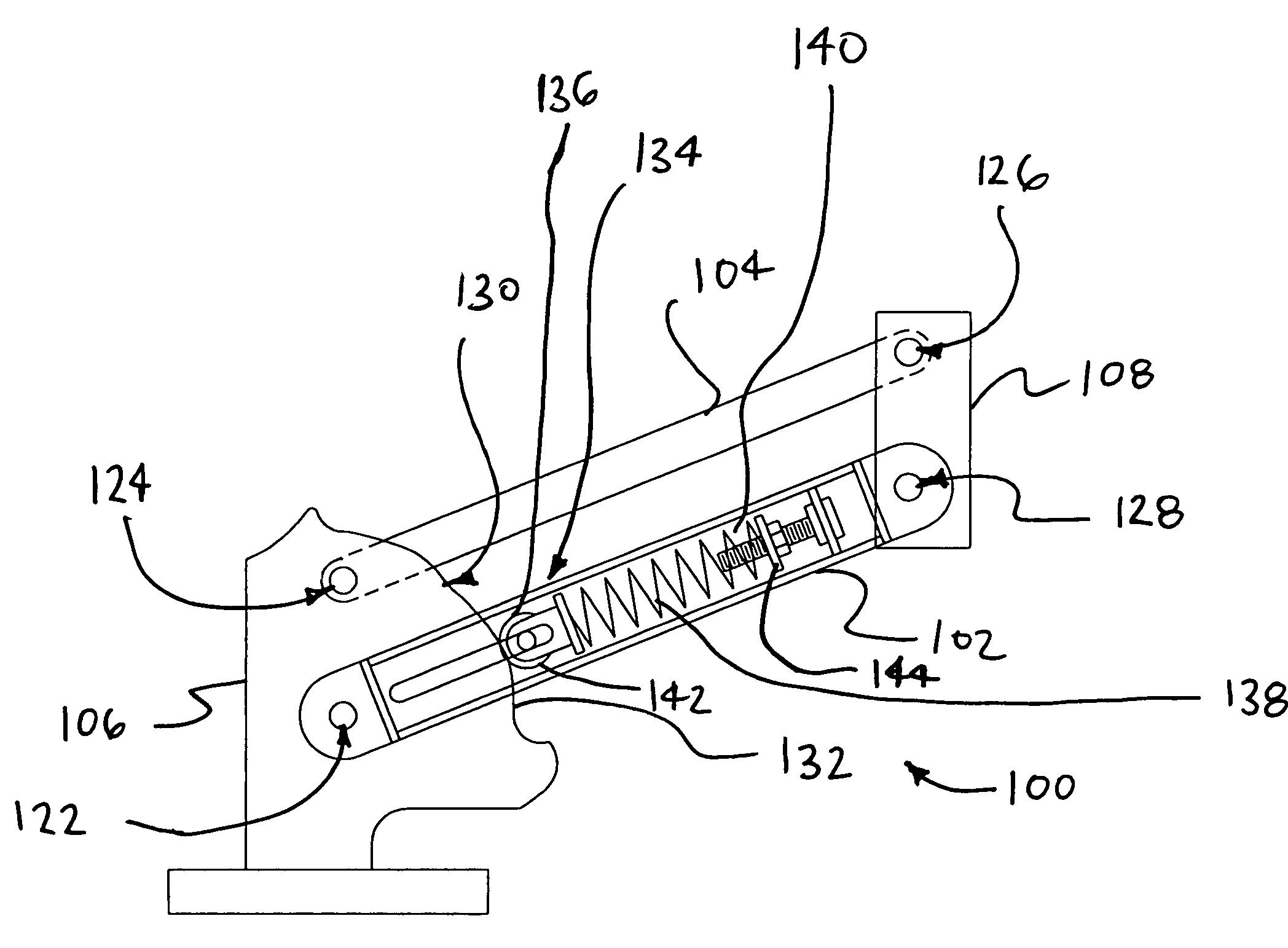
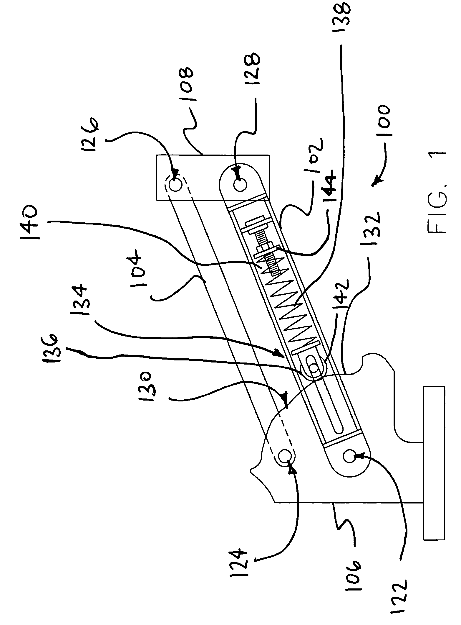
[0047]FIG. 1 is a diagrammatic representation of a support arm 100 in accordance with an exemplary embodiment of the present invention. Support arm 100 includes a first strut 102, a second strut 104, a proximal link 106, and a distal link 108. In the embodiment of FIG. 1, a proximal portion of the first strut 102 is pivotally coupled to proximal link 106 at a first pr...


PUM


Abstract

An apparatus for supporting a load is disclosed. A support arm in accordance with an exemplary embodiment of present invention comprises a first strut, a second strut, a proximal link, and a distal link. A proximal portion of the first strut is pivotally coupled to the proximal link at a first proximal joint. Additionally, a proximal portion of the second strut is pivotally coupled to the proximal link at a second proximal joint. A distal end of the second strut is pivotally coupled to the distal link at a second distal joint. A distal end of the first strut is pivotally coupled to the distal link at a first distal joint. The support arm also includes a cam mechanism comprising a cam and a cam follower.

Description

RELATED APPLICATIONS[0001]The present Application claims the benefit of U.S. Provisional Patent Application Ser. No. 60 / 441,143, filed Jan. 17, 2003.[0002]The present Application claims the benefit of U.S. Provisional Patent Application Ser. No. 60 / 471,869, filed May 20, 2003.[0003]The present Application claims the benefit of a U.S. Provisional Patent Application No. 60 / 492,015 filed on Aug. 1, 2003.[0004]The present Application is related to U.S. patent application Ser. No. 10 / 644,437 filed on Aug. 20, 2003.[0005]The entire disclosure of the above-mentioned patent applications is hereby incorporated by reference herein.FIELD OF THE INVENTION[0006]The present invention relates generally to an apparatus for supporting a load. More particularly, the present invention relates to an apparatus that is positionable, so that the location of a supported load can be changed from time to time. In some, but not necessarily all, cases the apparatus provides a substantially constant supporting ...

Claims


Application Information

Patent Timeline
IPC IPC(8): A47G29/00F16M11/04F16M11/10F16M11/24
CPCF16M11/04F16M11/10F16M11/105F16M11/2064F16M11/2092F16M11/24F16M2200/044F16M2200/063Y10S248/917Y10S248/923
Inventor SWEERE, HARRY C.WONG, THIEMAL-ZEBDEH, KHALIDERGUN, MUSTAFA A.
Owner ERGOTRON
Why Eureka
Try Eureka