Moving interleaved sputter chamber shields

Inactive Publication Date: 2008-10-30
NOVELLUS SYSTEMS
View PDF11 Cites 16 Cited by
  • Summary
  • Abstract
  • Description
  • Claims
  • Application Information

AI Technical Summary

Benefits of technology

[0022]In another aspect, the present invention is directed to a method of shielding a physical vapor deposition chamber. The chamber has a pedestal movable between a lowered loading and unloading position and a raised deposition processing position and is surrounded by chamber interior lower, side and upper walls. The chamber further includes a sputter target above the pedestal. The method comprises initially providing a shielding system having a pedestal shield secured to the pedestal and movable therewith between the lowered and raised positions. The pedestal shield surrounds and extends outward from the pedestal toward the chamber side or lower walls. There is also provided a sidewall shield extending substantially around

Problems solved by technology

Deposition of the metal on unwanted areas of the chamber walls can result in problems, including particles on the wafer.
Additionally, if the shield has a large surface area, additional process time is required for pumping

Method used


Image

  • Moving interleaved sputter chamber shields
  • Moving interleaved sputter chamber shields
  • Moving interleaved sputter chamber shields

Examples


Embodiment Construction

)

[0044]In describing the preferred embodiment of the present invention, reference will be made herein to FIGS. 1-20 of the drawings in which like numerals refer to like features of the invention.

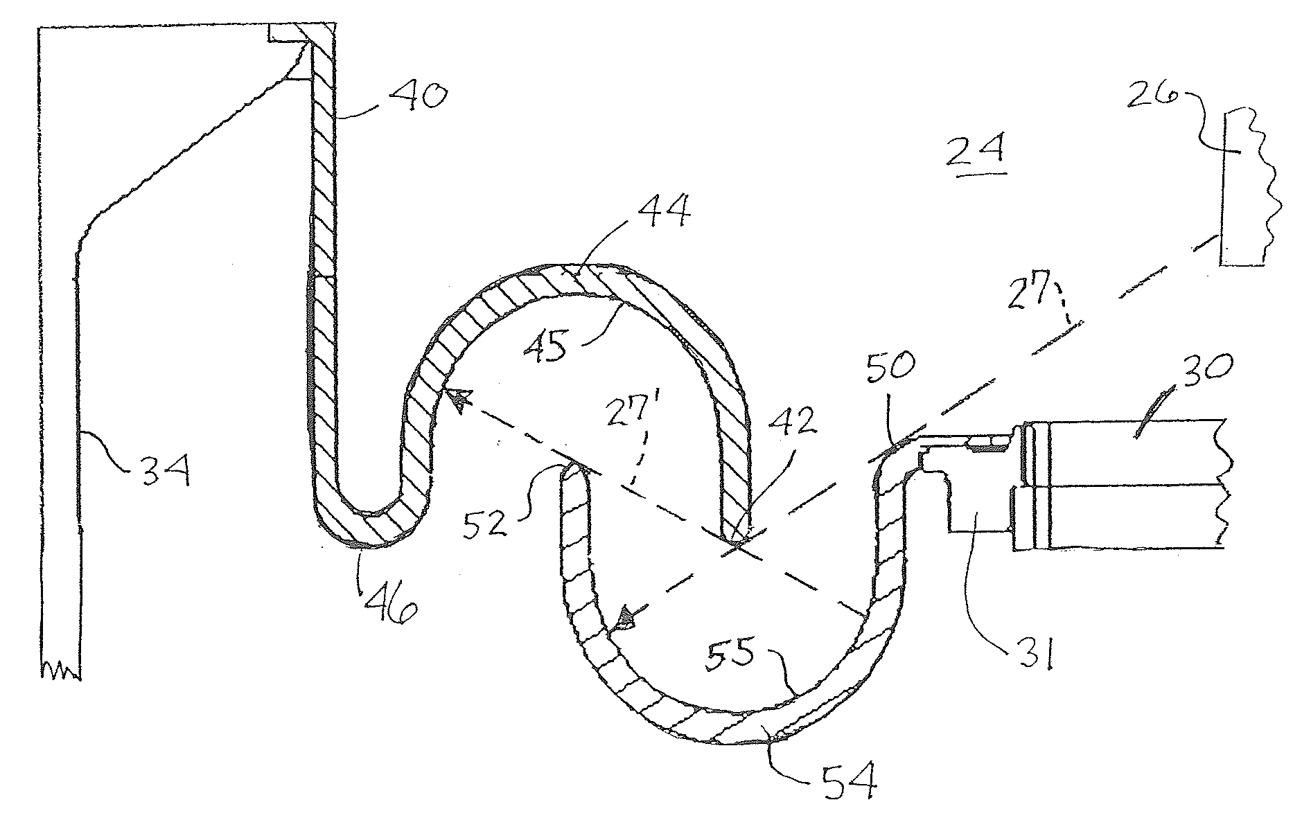
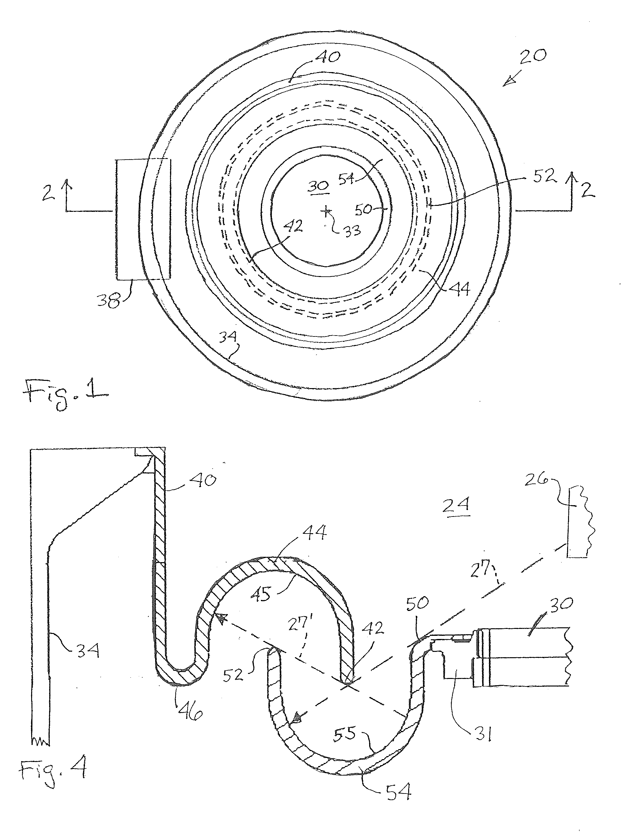
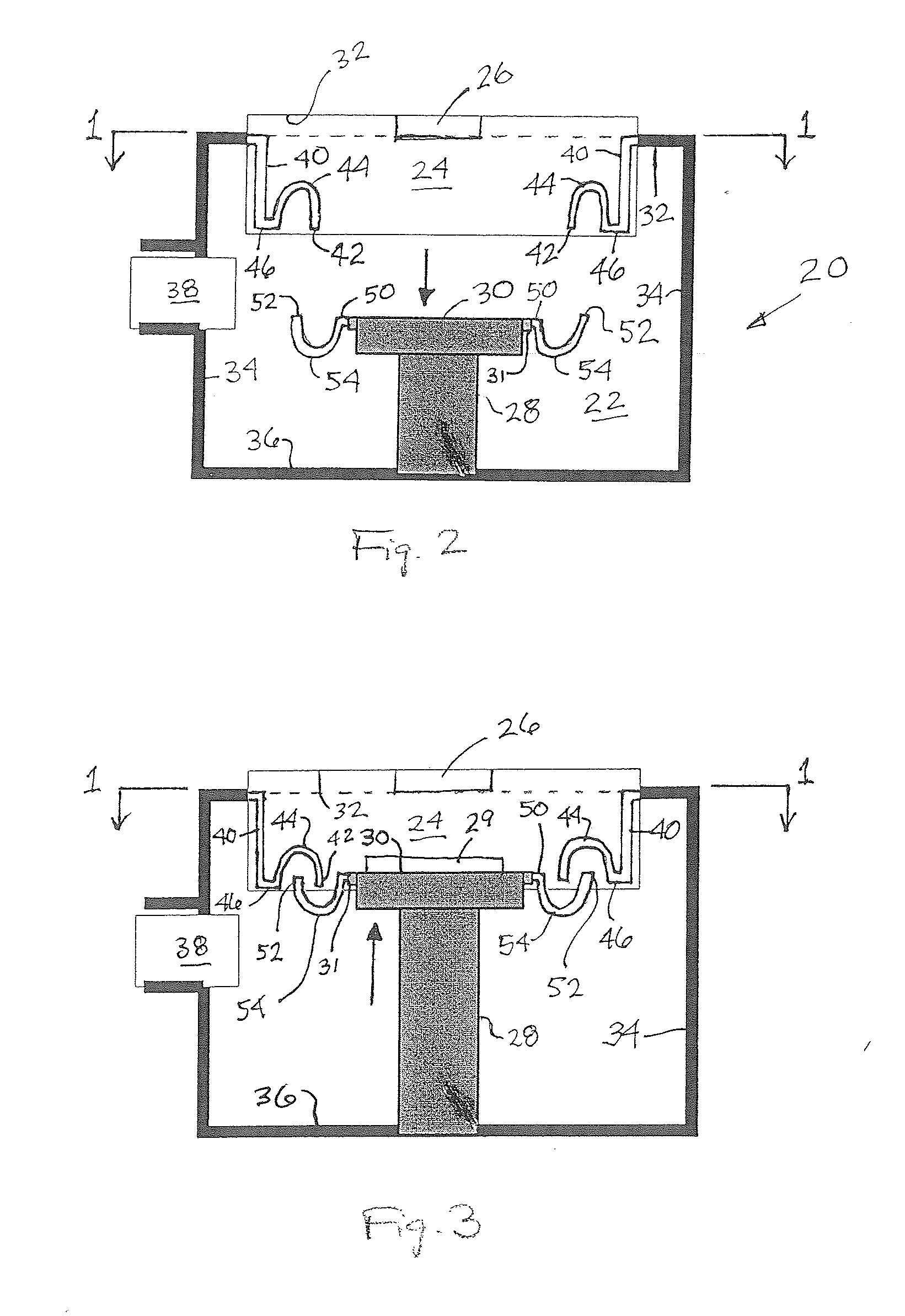
[0045]The present invention provides shielding system and method of shielding the interior walls of a sputter or PVD chamber using moving interleaved shielding segments. A first embodiment of the shield system of the present invention is depicted in FIGS. 1-4. In FIGS. 1, 2 and 3, a PVD deposition chamber 20 has an otherwise conventional vacuum valve or gate system 38 which permits wafers to be loaded into and removed from the chamber interior 22. The chamber interior has a central axis 33 and is bounded by lower wall 36, sidewall 34 and upper wall 32, and defines a generally cylindrical interior volume. Wafer holder or pedestal 30 is secured to movable support 28 along the central axis and may be positioned between a wafer loading and unloading position (FIG. 2) and a raised, processing pos...


PUM


Abstract

A shielding system for a physical vapor deposition chamber having a sputter target above the pedestal. The shielding system comprises a pedestal shield attachable to the pedestal and movable therewith. The pedestal shield surrounds and extends outward from the pedestal toward the chamber side or lower walls. The system also comprises a sidewall shield adapted to extend substantially around and within the chamber sidewalls, and downward from an upper portion thereof. The sidewall shield has a lower end extending inward and disposed adjacent the pedestal shield upper portion when the pedestal is in the raised position. The pedestal shield and sidewall shield cooperate, when the pedestal is in the raised position, to prevent line-of-sight deposition transmission from the sputter target to the side and lower walls of the deposition chamber.

Description

BACKGROUND OF THE INVENTION[0001]1. Field of the Invention[0002]This invention relates to devices for containing unwanted deposition (over-spray) in a deposition chamber used for processing semiconductor wafers and, more particularly, to a passive shielding device positioned inside a deposition chamber used for processing semiconductor wafers which shields deposition from the vacuum chamber and can be removed and replaced.[0003]2. Description of Related Art[0004]In the fabrication of semiconductor devices, a deposition chamber is used to deposit metal films on wafer surfaces using physical vapor deposition (PVD) techniques. The PVD apparatus is generally termed a sputtering apparatus and a wafer is placed inside a vacuum chamber within the deposition chamber, and is positioned on a wafer holder or pedestal. The wafer holder or pedestal is normally supported on the bottom wall of the vacuum chamber by insulating means, and the vacuum chamber is further equipped with a sputtering gas ...

Claims


Application Information

Patent Timeline
IPC IPC(8): C23C16/00
CPCC23C14/564H01J37/32504H01J37/34H01J2237/026
Inventor MARTINSON, ROBERTBOURDON, NORMANLAI, KWOK FAISHRIVASTAVA, DHAIRYASHUFFLEBOTHAN, PAUL
Owner NOVELLUS SYSTEMS
Why Eureka
Try Eureka