Single-use long-life faucet-mounted water filtration devices

a technology of water filtration device and single-use, applied in the direction of filtration separation, separation process, treatment involving filtration, etc., can solve the problem of not having removable or replaceable parts yet providing long-life operation, and achieve the effect of accurately distinguishing between flow and operation

Inactive Publication Date: 2005-05-05
CLARITY FILTERS
View PDF99 Cites 17 Cited by
  • Summary
  • Abstract
  • Description
  • Claims
  • Application Information

AI Technical Summary

Benefits of technology

[0014] A single-use faucet-mounted water filtration device is provided. The device is of uni-body construction and has no removable or replaceable parts yet provides long life operation. This arrangement makes the device more convenient to use compared with other devices that require frequent replacement of filter cartridges. The device is constructed with a minimum of components making it relatively small in size and less costly to manufacture. While compact, the device is able to hold enough filter media to allow for long life operation. The life of the water filtration device is dependent upon the type of filter media used, sizing and geometry of the filter media, and the sizing and geometry of water flow paths. For instance, water filtration devices having a useful life of 300 gallons or more can be made utilizing the teachings of the instant invention. Water filtration devices having useful lives smaller than 300 gallons may also be made utilizing the teachings of the instant invention. Performance indications as a function of integrated flow are indicated by a light emitting diode.
[0015] The main housing of the devices resides beneath the faucet neck and rearward of the water discharge point thus not obstructing the sink basin. A single-use device is provided for use in a kitchen sink and a device is provided for use in a bathroom sink. Unlike devices in the related art the bathroom embodiment of the single-use faucet filter is scaled to the small size of bathroom sinks and therefore practical for use in bathrooms. The bathroom filter device allows residential users to have the benefit of filtered water in close proximity to the bedroom avoiding the inconvenience of going to a kitchen sink for water during the night. In addition, because the bathroom device is small and disposable it may be taken with a traveler and installed in a hotel or motel room. Further, as travelers readily discern the differences between water and its tastes from one place to another it is highly desirable that the water filter be portable.
[0025] A filter performance indicator for use in a water filter which includes a gate having a first magnet affixed thereto and a filter boundary having hinges thereon forming a pivot thereon and a second magnet affixed thereto is also disclosed herein. The gate is pivotally affixed to the hinges and is movable in an arc between a first position when no flow impinges upon the gate and the first and second magnets are coupled together and a second position when flow does impinge upon the gate and the first and second magnets are not coupled together. A filter housing includes a sensor therein for sensing the presence of the gate and the first magnet when the gate is in the second position. The filter performance indicator accurately distinguishes between flow and no flow conditions. The gate includes a conically disposed structure extending from the rear side or end thereof which coacts with a cylindrically extending passageway which extends from the filter boundary.
[0027] It is an object of the present invention to provide a water filtration device which is disposable and provides an indication as to when the filter should be disposed.
[0030] It is an object of the present invention to provide a water filtration device at reasonable cost which is disposable and which is faucet mounted.
[0037] It is an object of the present invention to provide a reliable gate position sensing system which accurately distinguishes between flow and no flow conditions.

Problems solved by technology

The device is of uni-body construction and has no removable or replaceable parts yet provides long life operation.

Method used


Image

  • Single-use long-life faucet-mounted water filtration devices
  • Single-use long-life faucet-mounted water filtration devices
  • Single-use long-life faucet-mounted water filtration devices

Examples


first embodiment

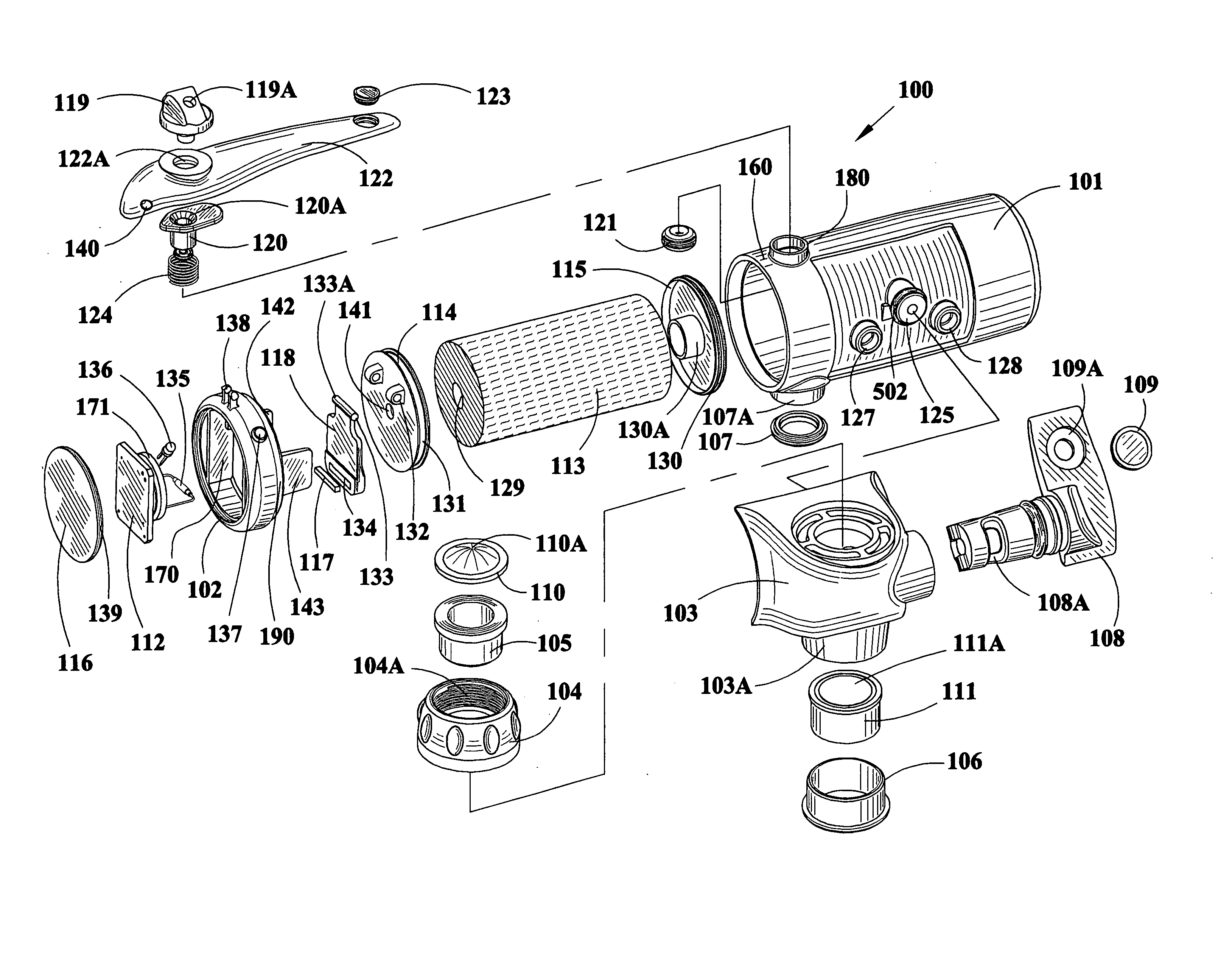
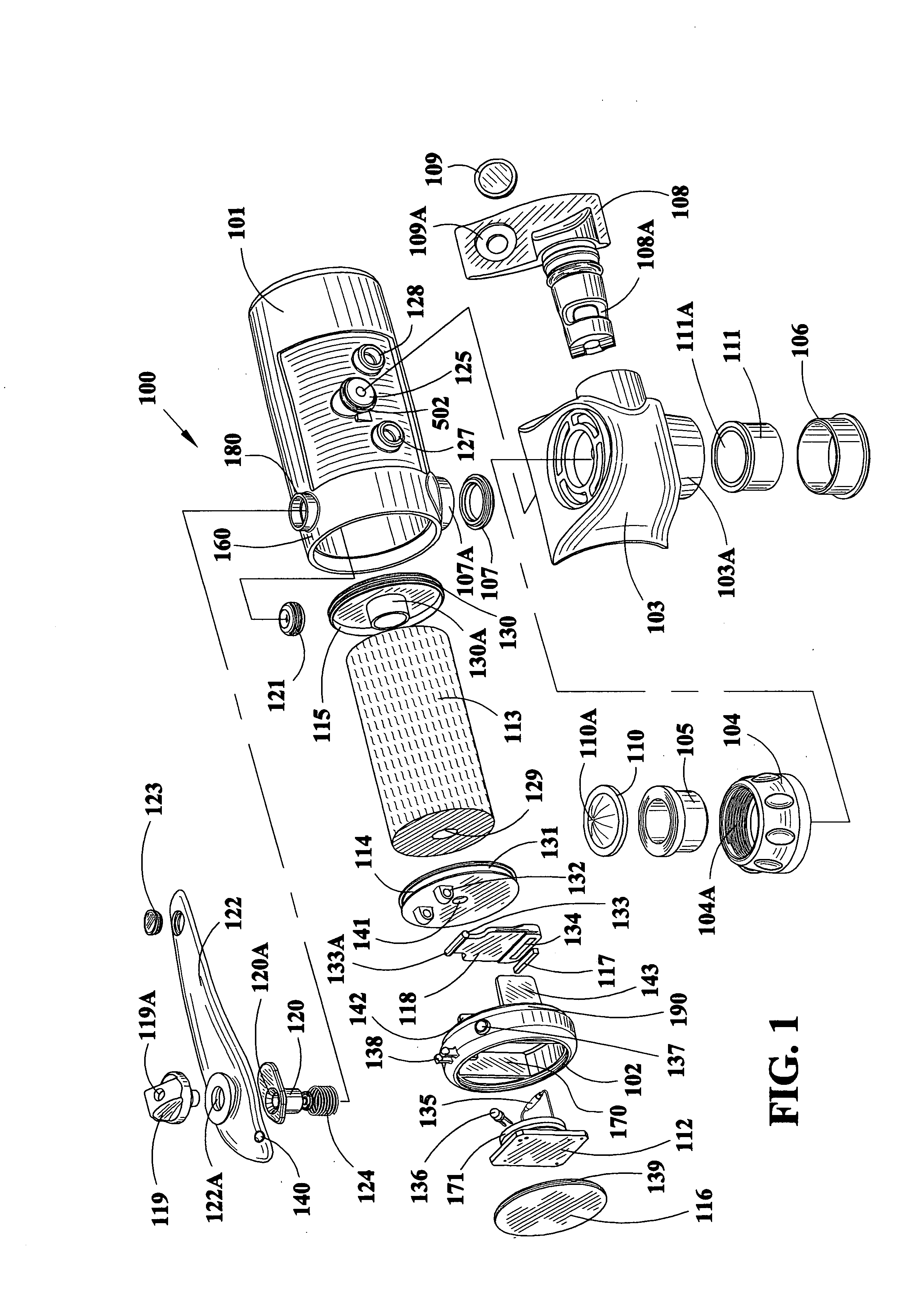
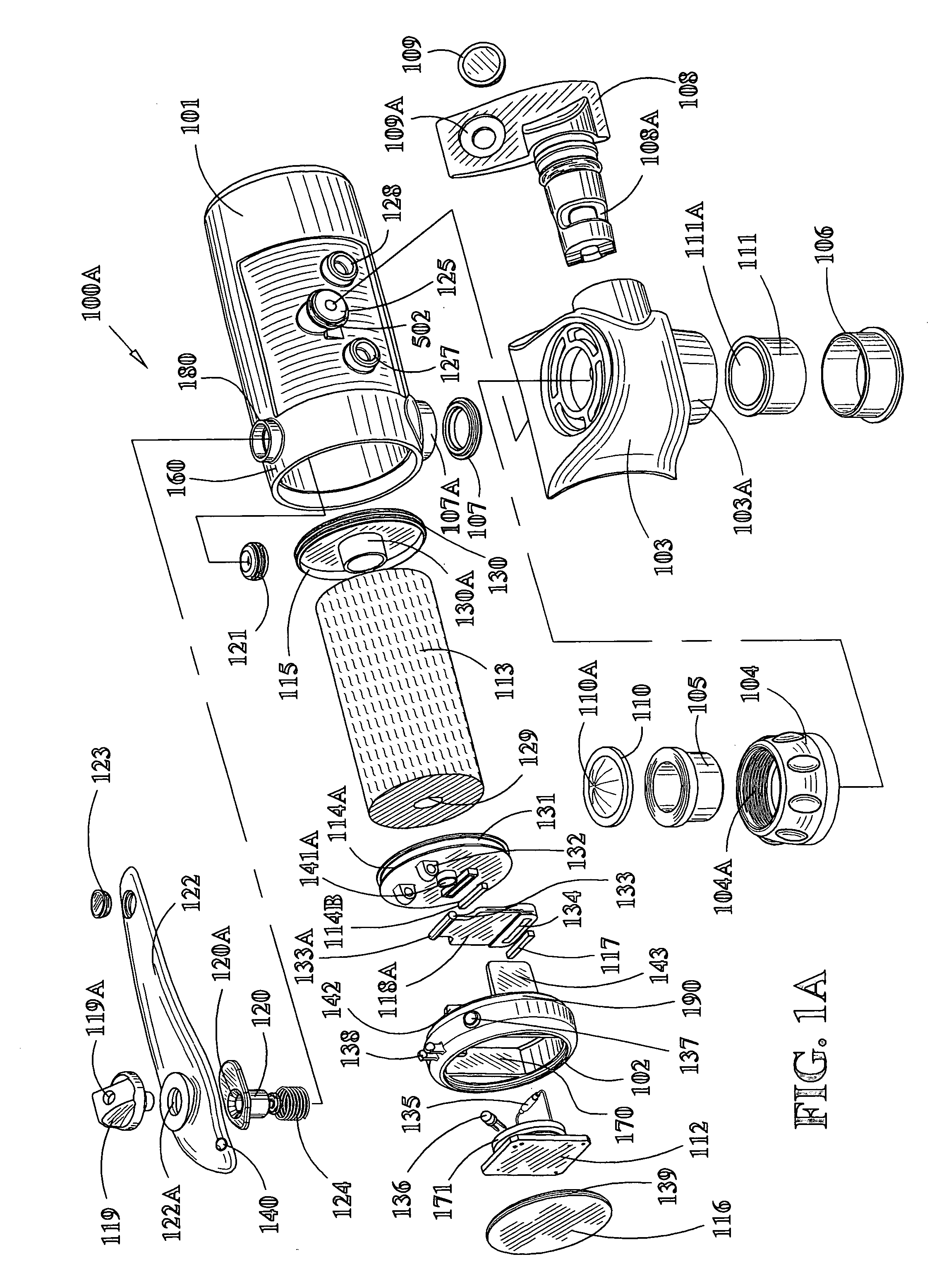
[0119] Referring to FIG. 1, an exploded assembly view of the water filtration device 100, the various components of the single-use faucet mounted water filter are shown. Filter 113 is illustrated having a longitudinal bore 129 therethrough. Filter 113 is illustrated without a filter pre-wrap in this view but such a pre-wrap 495 is specifically within the scope of this invention and is illustrated in FIGS. 4G and 4H. The filter is preferably a carbon block but may be a fiber bundle or granular activated carbon. Further, the carbon block may include bacteriastic materials, ion exchange resins and zeolites to assist in its filtration activity. End caps 114 and 115 are affixed to said filter with a hot melt adhesive applied to the entire mating surfaces of end caps 114 and 115 including but not limited to the dowel portions thereof such as dowel 130A on right end cap 130. Once filter 113 is affixed to end caps of filter 114, 115, the subassembly is inserted into the filter housing 101. ...

second embodiment

[0166]FIG. 18 is a perspective view 1800 of the front housing of the FIG. 18 employs reference numerals like FIG. 4. FIG. 18A is a cross-sectional view taken along the lines 18A-18A of FIG. 18. Reference numeral 1801 indicates the wall to which the collar lock 1505 is welded and reference numeral 1804 indicates the floor upon which the collar lock 1804 sits at the time it is welded. Mold recesses 1802 are from the molding process. Groove or recess 1816 receives the seal from the valve 108. Cavity 1831 receives the valve 108. Referring to FIG. 18A, stop 1807A is illustrated which engages ridges 602 on valve 108. Stop 1807A is also illustrated in FIG. 18B, a cross-sectional view taken along the lines 18B-18B of FIG. 18. Tapered bore 1812 is illustrated by the circular lines in FIG. 18A.

[0167] Bore 1822 includes stepped portions 1813 and 1829. Inlet 1808 is shown leading to valve cavity 1831. Outlet 1814 and outlet 1809 are also shown in FIG. 18A. When valve 108 is positioned as illus...

third embodiment

[0179]FIG. 3E is a cross-sectional view 300E of the water filtration device with a different left end cap 118A and a second magnet 114B employed. Conical protrusion 118B extends from the rearward side of the gate 118A. FIG. 3E illustrates the no flow condition and the gate is in the first position. In this condition magnet 117 which resides in the gate 118A is coupled to magnet 114B which resides in the end cap 114A. It is the coupling effect of the magnets which ensures that the magnet 117 does not unintentionally and improperly actuate the reed switch and indicate a flow condition.

[0180] Magnets 117 and 114B are attractive magnets and are oriented such that they attract one another. Magnet 117 is secured within the gate 118A and magnet 114B is secured within left end cap 114A. A potting compound or adhesive may be used to secure the respective magnet within the gate 118A and the left end cap 114A. Therefore, as the magnets are attractive the gate is also attracted toward the left ...


PUM

PropertyMeasurementUnit
diameteraaaaaaaaaa
diameteraaaaaaaaaa
lengthaaaaaaaaaa

Abstract

Single-use long-life faucet mounted water filtration devices are disclosed. A bathroom water filtration device having two outlets for filtered water is disclosed. Additionally, a fountain head is included for use in the bathroom water filtration device. The water filtration device is of unibody construction formed by ultrasonically welding certain parts thereof together. Since the devices disclosed are disposable, no filter replacement or other maintenance is performed. A gate, magnet(s), sensor and electronics provide an indication of filter performance enabling disposal of the water filtration device and installation of a new device. A kitchen water filtration device is larger than the bathroom device. Both the kitchen and bathroom water filtration devices are small and are mounted behind the faucet connection so as to facilitate full utilization of the sink or wash basin.

Description

[0001] This patent application is a continuation in part of copending U.S. patent application Ser. No. 10 / 613,950 filed Jul. 3, 2003 and claims priority thereto.FIELD OF INVENTION [0002] The field of the invention is water filtration devices. BACKGROUND OF THE INVENTION [0003] The demand for pure water continues to grow rapidly due to increasing concerns about the quality and safety of tap water, the popularity of water as a beverage (instead of soda and alcohol) and the growing awareness that most people do not drink enough water as prescribed by the medical community. [0004] Water is supplied from municipal water systems (many of which are aging), private water systems and wells in the United States. Frequently, this water has poor taste, particulates, unwanted odors and in many cases contaminants contained in it. Municipal water is commonly treated with chlorine to eliminate bacterial contaminants. Chlorine adds what most people feel is an unpleasant taste and odor. Water conditi...

Claims


Application Information

Patent Timeline
Patent Type & Authority Applications(United States)
IPC IPC(8): B01D27/00B01D35/143C02F1/00C02F1/28
CPCB01D27/005B01D35/143C02F1/003C02F1/283C02F2209/445C02F2307/06B01D27/08B01D27/101B01D35/04B01D35/30
Inventor WARREN, WILLIAMLEWIS, GORDONRIZZARI, ROBERT
Owner CLARITY FILTERS
Why Eureka
Try Eureka