Multilayer wiring circuit board
a wiring circuit board and multi-layer technology, applied in the direction of thermoplastic polymer dielectrics, dielectric characteristics, semiconductor/solid-state device details, etc., can solve the problems of difficult to make the circuit structure fine, and become impossible to remove high-frequency noise, so as to reduce the inductance of the circuit, suppress the generation of high-frequency noise, and improve the effect of high-frequency switching operation
- Summary
- Abstract
- Description
- Claims
- Application Information
AI Technical Summary
Benefits of technology
Problems solved by technology
Method used
Image
Examples
second embodiment
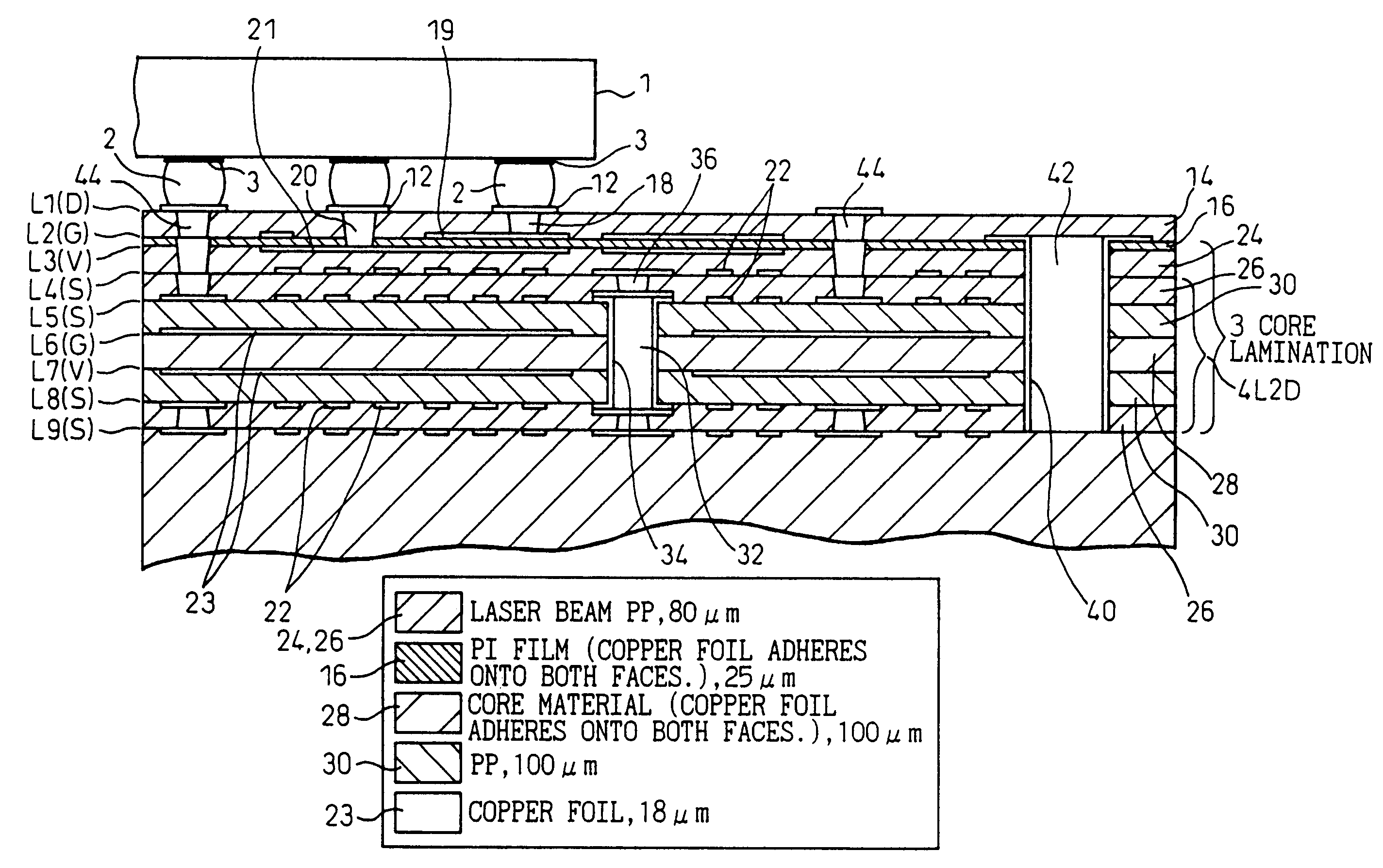
[0102]FIG. 10 is a sectional view of the multilayer wiring circuit board of the present invention.
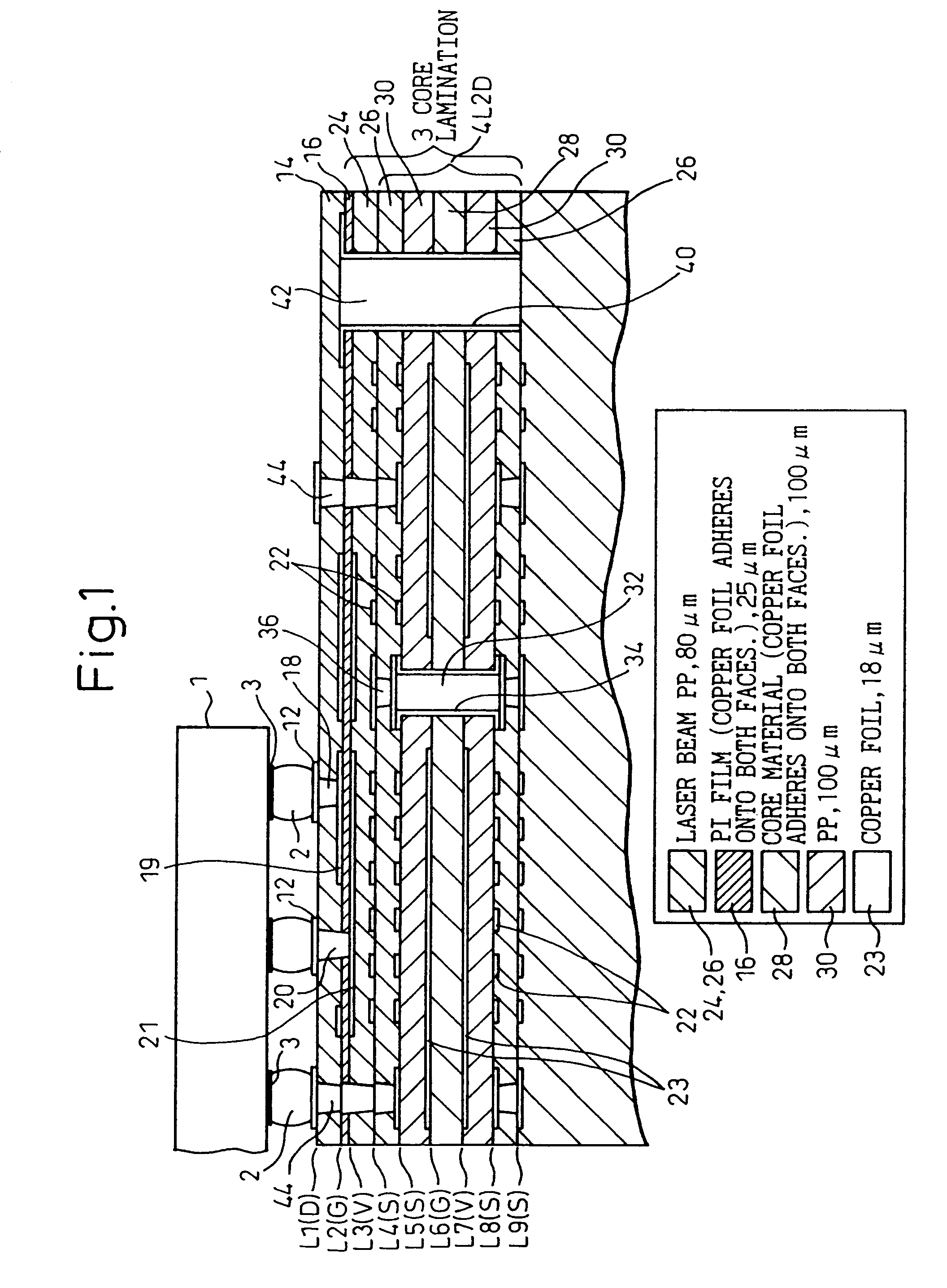
[0103]In the same manner as that of the first embodiment, concerning the semiconductor chip 1 mounted on the multilayer wiring circuit board of the second embodiment, it is possible to mount any of the bare chip, the ball grid array (BGA) type chip having bumps of the surface mounting type, the LGA type chip having no bumps and the part of QFA type having leads. FIG. 10 is a view showing an example in which the semiconductor chip 1 of the ball grid array (BGA) type having the solder bumps 2 is shown. The electrode pads 3 of this semiconductor chip 1 are connected with pad portions on the conductive pattern 19 provided on the multilayer wiring circuit board via the solder bumps 2.
[0104]The second layer L2 is formed as a ground layer. However, as described later, the conductive pattern connected with the electric power source layer and the signal layer is formed on this second layer. The ...
first embodiment
[0105]Between the uppermost surface layer L1 and the ground layer L2, there is provided a surface layer. Instead of the prepreg layer (insulating film) described in the first embodiment, which can be subjected to laser beam patterning, the surface layer is composed of the solder resist layer 14 in this embodiment. The thickness of this solder resist layer 14 is approximately 20 μm. Portions on this solder resist layer 14, in which the solder bumps 2 of the semiconductor chip 1 are joined, are open.
[0106]In the same manner as that of the first embodiment, as the material of the insulating film 16 provided between the ground layer L2 and the electric power source layer L3, it is preferable to use a polyimide film having a thermoplastic adhesion property on both sides. It is possible to use a polyimide film (laser PP) which can be subjected to laser beam patterning, for example, it is possible to use a polyimide film of about 15 μm thickness.
[0107]Concerning the solder resist layer 14 ...
third embodiment
[0119]Accordingly, in the second and the third embodiment, it is unnecessary to provide processes in which the copper foil 48 shown in FIG. 6 is subjected to laser beam machining, plating and patterning.
[0120]In the second and the third embodiment, concerning the copper wiring patterns 19, 21 formed on both faces of the polyimide film 16, one is formed as a ground layer, and the other is formed as an electric power source layer. A portion of the copper wiring pattern 19 on the upper side is connected with the other layer through the conductive vias or copper plating and also connected with the signal layer through the conductive vias or copper plating.
[0121]In any embodiment, both the ground layer and the electric power source layer can be arranged at the closest positions in the thickness direction of the multilayer wiring circuit board compared with the signal layer. Due to the foregoing, it becomes possible to reduce the inductance of the circuit, and the generation of noise in t...
PUM
| Property | Measurement | Unit |
|---|---|---|
| frequency | aaaaa | aaaaa |
| thickness | aaaaa | aaaaa |
| thickness | aaaaa | aaaaa |
Abstract
Description
Claims
Application Information
 - R&D
- Intellectual Property
- Life Sciences
- Materials
- Tech Scout
- Unparalleled Data Quality
- Higher Quality Content
- 60% Fewer Hallucinations
Browse by: Latest US Patents, China's latest patents, Technical Efficacy Thesaurus, Application Domain, Technology Topic, Popular Technical Reports.
© 2025 PatSnap. All rights reserved.Legal|Privacy policy|Modern Slavery Act Transparency Statement|Sitemap|About US| Contact US: help@patsnap.com


