Wavelength detector

a detector and wavelength technology, applied in the field of sensing devices, can solve the problems of surface polarization sensitive, system described above susceptible to errors, etc., and achieve the effects of compact and stable radiation measurement devices, reducing polarization-dependent errors, and improving the level of error reduction

Active Publication Date: 2007-08-07
MITUTOYO CORP
View PDF10 Cites 17 Cited by
  • Summary
  • Abstract
  • Description
  • Claims
  • Application Information

AI Technical Summary

Benefits of technology

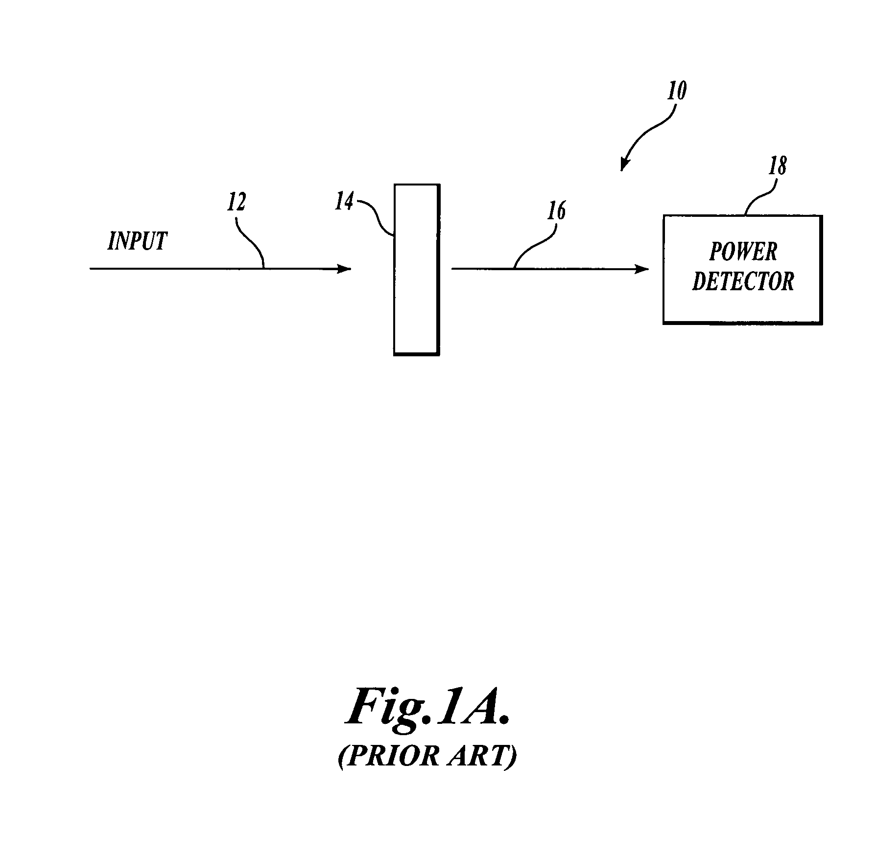
[0009]In particular, the systems described above that compensate for power source fluctuations are susceptible to errors that depend on the polarization orientation of the input radiation. This is because P-polarized and S-polarized components of a beam of radiation are transmitted or reflected in different proportions when they are incident on a polarization-sensitive transmissive or reflective surface, such as a beamsplitter or filter at an angle that is not normal to the surface. Transmission and reflection gratings are also polarization sensitive, regardless of the input beam angle of incidence. In contrast to the foregoing wavelength detectors, the present invention recognizes that such errors are significant at a level of accuracy that can be provided by some of the embodiments described herein, and provides a system and method for reducing polarization-dependent errors in a radiation measurement device, such as a wavelength detector. Furthermore, various embodiments of the present invention also provide improved levels of error reduction for errors due to other causes, such as power variations and environmental parameters variations. Still further, various embodiments of the present invention provide particularly compact and stable radiation measurement devices.
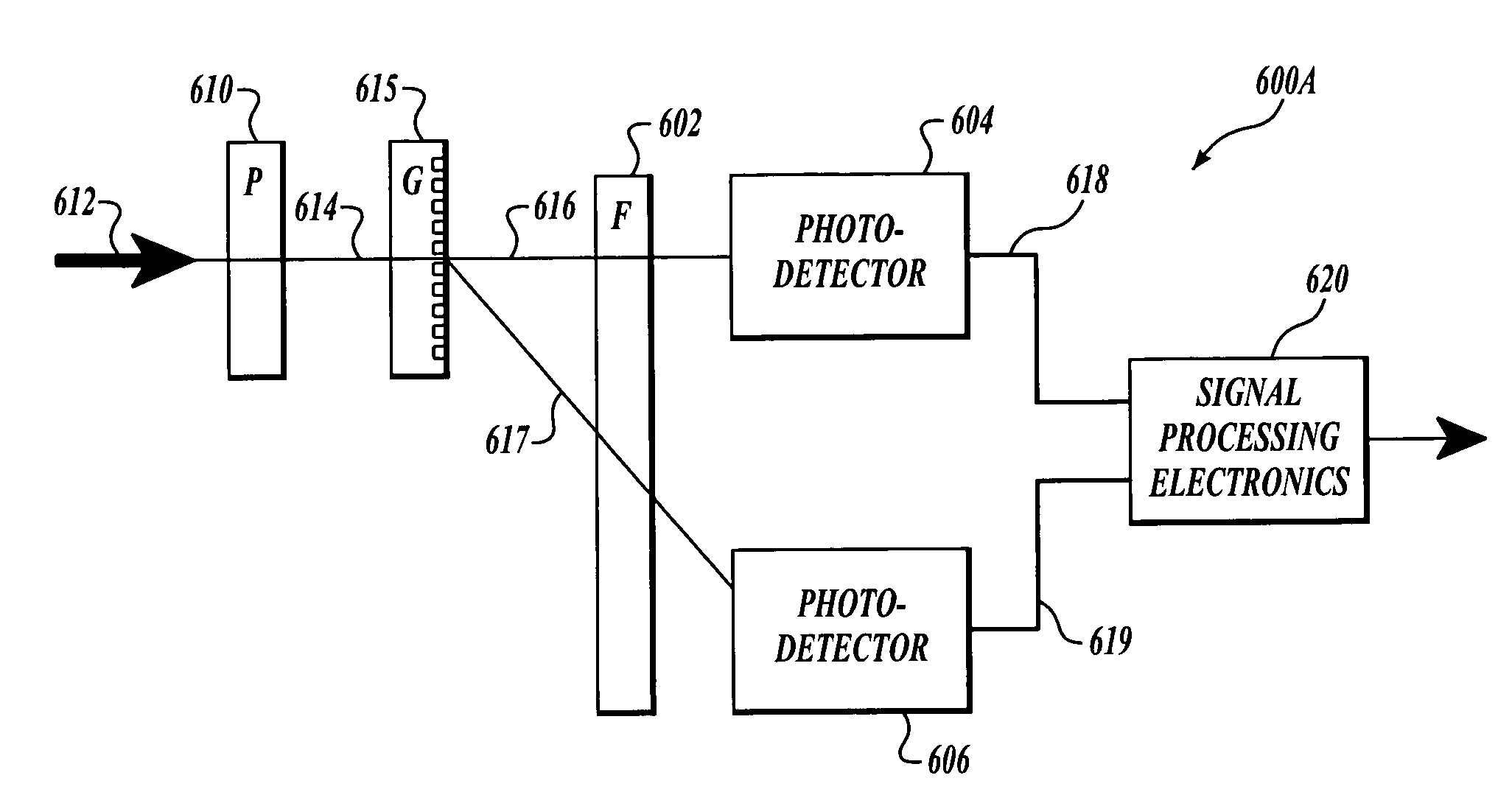
[0012]In various embodiments of the present invention, a radiation measurement device for determining a wavelength-related characteristic of radiation from a radiation source is provided. In various exemplary embodiments, the radiation measurement device includes a wavelength-dependent optical element (e.g., bandpass filter), an optical power-measuring detector (e.g., photodetector), a polarization-sensitive reflective and / or transmissive surface, and one or more linear polarizers. At least a first optical beam is transmitted along a first optical path that includes the wavelength-dependent optical element, the polarization-sensitive reflective and / or transmissive surface, and the one or more linear polarizers, and arrives at a first optical power-measuring detector. The polarization-sensitive reflective and / or transmissive surface receives the optical beam and transmits it along the first optical path. The wavelength-dependent optical element modifies the optical power of the first optical beam before or after the polarization-sensitive reflective and / or transmissive surface, and the first optical beam is received by the optical power-measuring detector along the first optical path. The one or more linear polarizers are placed at selected locations along the first optical path prior to the first optical power-measuring detector to substantially eliminate polarization dependent errors. For example, the linear polarizer may be placed prior to or after the wavelength-dependent optical element, and further, two or more linear polarizers may be placed, for example, both prior to and after the wavelength-dependent optical element, if desired.
[0013]In accordance with one aspect of the invention, the inclusion of one or more linear polarizers ensures that the beam(s) incident onto the polarization-sensitive reflective and / or transmissive surface(s) is received and / or transmitted along an optical path with a substantially fixed state of polarization, regardless of the polarization state of the original input optical beam. Thus, polarization-dependent errors that may otherwise be caused can be significantly reduced or eliminated.
[0020]The present invention also provides a method for providing at least one signal usable for determining wavelength-related characteristics of radiation from a radiation source in a manner that is substantially independent of the orientation of the polarization of the radiation. The method comprises generally five steps. The first step comprises inputting a first optical beam from the radiation source along a first optical path that includes at least one polarization-sensitive surface, of any of the previously indicated types. The second step comprises receiving the first optical beam and outputting a first filtered beam from a first wavelength-dependent optical element along the first optical path. The third step comprises receiving the first filtered beam output by the first wavelength-dependent optical element with a first optical power-measuring detector placed along the first optical path. The fourth step comprises outputting a first detection signal from the first optical power-measuring detector. Finally, the fifth step comprises linearly polarizing the radiation included in the first optical beam and / or the first filtered beam. In various respective embodiments, the fifth step of linearly polarizing the radiation included in the first optical beam and / or the first filtered beam may occur at various respective points along the first optical path that are before the first optical power-measuring detector. The method of the present invention, including the step of linearly polarizing the radiation included in the first optical beam and / or the first filtered beam, significantly reduces or eliminates any polarization-dependent errors in one or more signals used for determining a wavelength-related characteristic of radiation.

Problems solved by technology

In particular, the systems described above that compensate for power source fluctuations are susceptible to errors that depend on the polarization orientation of the input radiation.
The addition of a transmissive or reflective grating to a surface may also make the surface polarization sensitive, even at normal angle of incidence.

Method used


Image

  • Wavelength detector
  • Wavelength detector
  • Wavelength detector

Examples


Embodiment Construction

[0038]In general, the proportion of incident radiation power that is transmitted by any polarization-sensitive reflective or transmissive surface, including a surface of a filter and / or a beam dividing element, is affected both by its angle of incidence and also by the polarization state of the radiation (i.e., the relationship between its P-polarized component and S-polarized component). FIG. 4 illustrates how the transmission of a light beam through an air / glass interface, with the glass having a refractive index of 1.57, varies based on an angle of incidence, and also based on the polarization state of the light beam. Transmission curves 410 and 412 correspond to incident light beams that are 100% P-polarized and 100% S-polarized, respectively. A curve 414 shows the difference in transmission between the transmission curves 410 and 412. At normal incidence (0° angle of incidence), the transmission characteristic of light is the same for both P-polarized polarized and S-polarized ...


PUM

PropertyMeasurementUnit
angle of incidenceaaaaaaaaaa
refractive indexaaaaaaaaaa

Abstract

A radiation measurement device for determining a wavelength-related characteristic of radiation from a radiation source is provided. The device includes a wavelength-dependent optical element (e.g., bandpass filter), and an optical power-measuring detector (e.g., photodetector). At least one optical beam is incident onto a polarization-sensitive reflective and / or transmissive surface positioned along an optical path of the device, is transmitted by the wavelength-dependent optical element, and is received by the optical power-measuring detector along the optical path. The radiation measurement device further includes a linear polarizer placed along the optical path prior to the optical power-measuring detector. In operation, the linear polarizer ensures that the beam received from the polarization-sensitive reflective and / or transmissive surface has a substantially fixed state of polarization, regardless of the polarization state of the original incident optical beam, to thereby reduce or eliminate uncontrolled polarization-dependent errors in the radiation measurement device.

Description

FIELD OF THE INVENTION[0001]The invention relates to a sensing device and, more particularly, to a method and system for measuring values related to the wavelength and / or frequency of a radiation source.BACKGROUND OF THE INVENTION[0002]Certain measurement applications require measuring the wavelength or frequency, or related shifts, of a radiation source to very high levels of resolution over a relatively small wavelength range. Examples include high resolution interferometric type encoders, various non-contact profilometer sensors, applications in the telecommunications industry, and spectroscopy, as well as general laboratory applications. In addition, for many applications, the measurement must be conducted within a small space and at a low cost. Several methods are commonly used for wavelength measurement, including spectrometers, interferometers, and transmission through optical filters.[0003]FIG. 1A shows a simple known measurement system 10 for measuring wavelength shift usin...

Claims


Application Information

Patent Timeline
Patent Type & Authority Patents(United States)
IPC IPC(8): G01J1/42G01N21/25G01J9/00G01J3/28
CPCG01J9/00
Inventor FELDMAN, MARK
Owner MITUTOYO CORP
Why Eureka
Try Eureka