Vehicle information recording system

a vehicle information and recording system technology, applied in the field of vehicle information recording system, can solve the problems of accident analysis, accident cannot be specifically analyzed, accident is analyzed,

Inactive Publication Date: 2007-08-07
PANASONIC INTELLECTUAL PROPERTY CORP OF AMERICA
View PDF19 Cites 339 Cited by
  • Summary
  • Abstract
  • Description
  • Claims
  • Application Information

AI Technical Summary

Benefits of technology

[0015]Furthermore, the other vehicle data specifying the other vehicle that is seen in the aforesaid picture data is added to that picture data. Since the searching unit searches for the picture data based on this other vehicle data, those who analyze the accident can easily search for the aforesaid picture data so as to acquire the desired picture data.
[0031]According to this structure, the emergency contact station can be notified of an occurrence of an accident immediately and without fail.

Problems solved by technology

However, according to both of these conventional devices, an accident is analyzed based on the data which is acquired by the vehicle that is involved in the accident.
Therefore, there is a problem in that the accident is analyzed based on only the pictures which are taken by the camera in the vehicle that is involved in the accident.
Therefore, there is a problem in that clear circumstances of the accident are not available, and thus, the accident cannot be specifically analyzed.
There is also a problem in that the data such as the pictures cannot be acquired just after the accident when the in-vehicle camera is damaged, and thus, the accident cannot be specifically analyzed.

Method used


Image

  • Vehicle information recording system
  • Vehicle information recording system
  • Vehicle information recording system

Examples


first embodiment

The First Embodiment

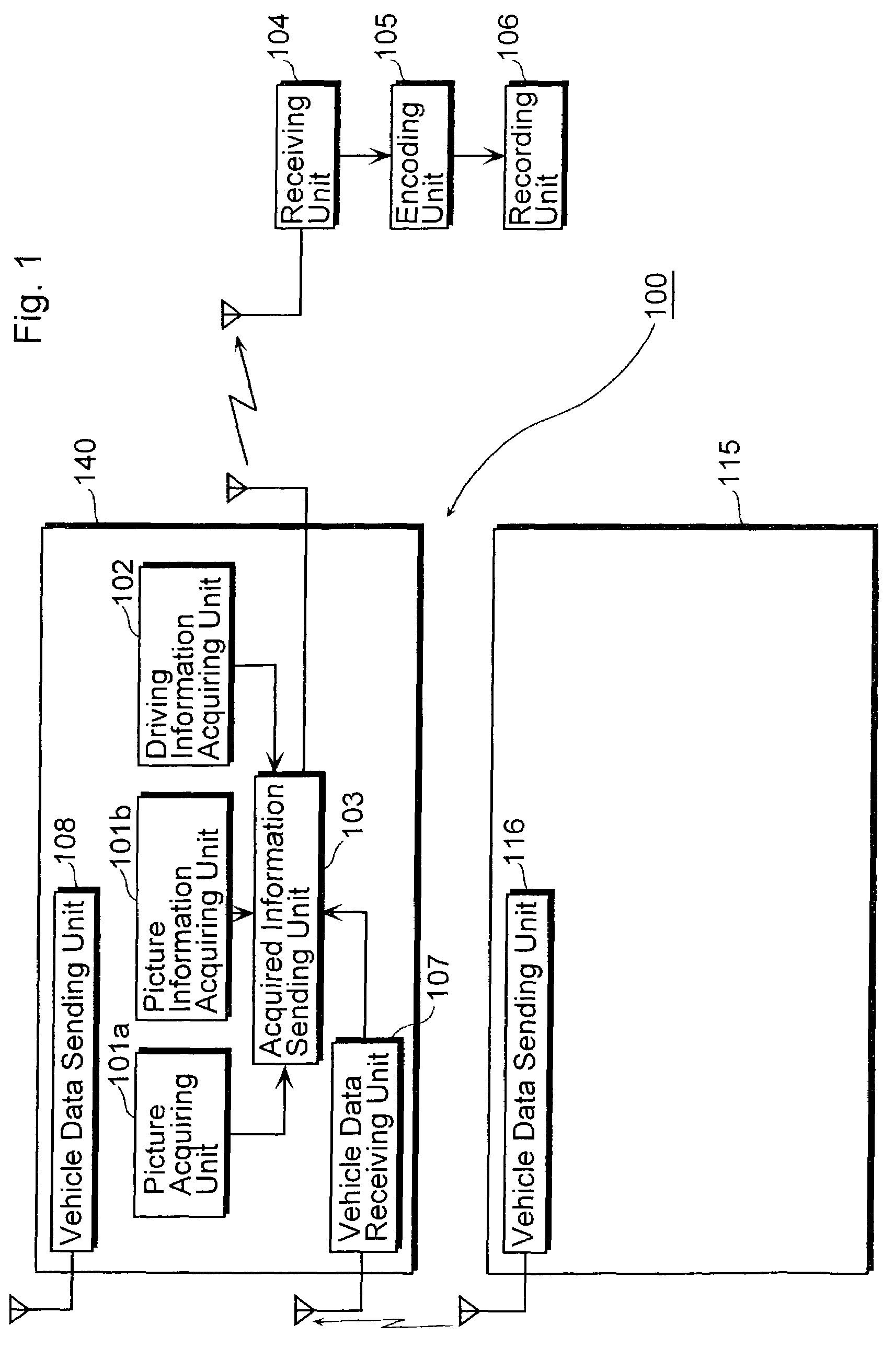
[0050]The first embodiment of the present invention will be explained with reference to the drawings. FIG. 1 is a block diagram showing an overall structure of the vehicle information recording system according to the first embodiment of the present invention.

[0051]The vehicle information recording system 100 includes an in-vehicle information acquiring unit 140 which is mounted in a vehicle such as a car. The in-vehicle information acquiring unit 140 includes a picture acquiring unit 101a, a picture information acquiring unit 101b, a driving information acquiring unit 102, a vehicle data receiving unit 107, a vehicle data sending unit 108, and an acquired information sending unit 103. The vehicle information recording system 100 also includes an in-vehicle information acquiring unit 115 which is mounted in another vehicle. The in-vehicle information acquiring unit 115 includes a vehicle data sending unit 116. The vehicle information recording system 100 also inc...

second embodiment

The Second Embodiment

[0212]The second embodiment of the present invention will be explained with reference to the drawings.

[0213]FIG. 14 is a block diagram showing an overall structure of the vehicle information recording system according to the second embodiment of the present invention. In FIG. 14, the same reference numbers are assigned to the same units as those units described above with reference to FIG. 1, and the explanation thereof will be omitted.

[0214]The vehicle information recording system 160 shown in FIG. 14 is different from vehicle information recording system 100 shown in FIG. 1 in that the vehicle information recording system 160 additionally includes a driving situation determining unit 150 that determines a driving situation of a vehicle based on the information that is acquired by the driving information acquiring unit 102.

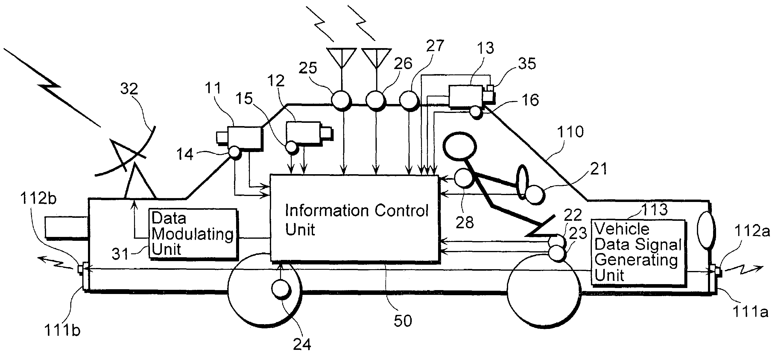
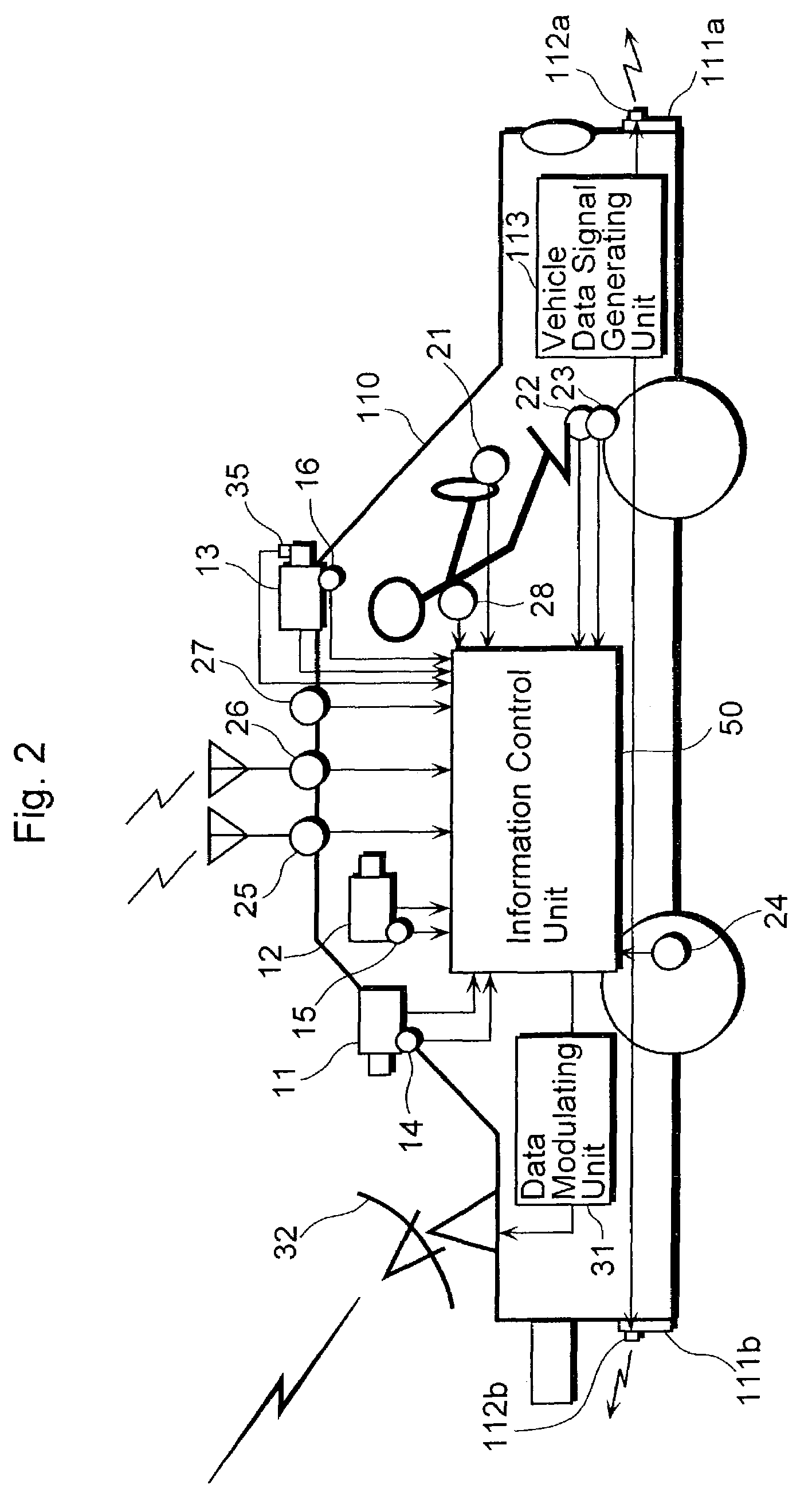
[0215]FIG. 15 is a diagram showing how the respective units in the vehicle information recording system 160 are mounted on the vehicle 110.

[...


PUM


Abstract

A vehicle information recording system 100 includes a picture acquiring unit 101a placed in a vehicle that takes a picture of surroundings and generates picture data showing the picture, a vehicle data receiving unit 107 placed in the vehicle that receives other vehicle data concerning another vehicle shown in the picture acquired by the picture acquiring unit 101a, an acquired information sending unit 103 placed in the vehicle that sends data including the picture data and the other vehicle data outside of the vehicle, a receiving unit 104 placed outside of the vehicle that receives the data sent by the acquired information sending unit 103, an encoding unit 105 placed outside of the vehicle that encodes the other vehicle data among the data received by the receiving unit 104 and adds the encoded data to the picture data as related data, and a recording unit 106 placed outside of the vehicle that records the picture data to which the other vehicle data is added by the encoding unit 105.

Description

BACKGROUND OF THE INVENTION[0001](1) Field of the Invention[0002]The present invention relates to a vehicle information recording system for recording information concerning a vehicle.[0003](2) Description of the Related Art[0004]Recently, there have been an increasing number of devices with functions of supporting a driver's recognition, judgment and operation based on information that is obtained from various types of sensors which are mounted in a vehicle such as a car.[0005]For example, a system for acquiring information such as weather, temperature, humidity and traffic condition and offering such information to a driver has been realized. Also, other systems have been under study, such as a system for giving a warning to a driver while driving in foreseeable danger based on the comparison between lane markers, traffic lights and speed signs that are obtained by pictures taken by an in-vehicle camera and separately calculated vehicle speed data and control data, and a system fo...

Claims


Application Information

Patent Timeline
Patent Type & Authority Patents(United States)
IPC IPC(8): G01C21/28G07C5/00G07C5/08
CPCG07C5/008G07C5/0891
Inventor KAWASAKI, YOSHITERUKOBAYASHI, TADASHISENDA, KEIICHIMOCHIZUKI, YOSHIYUKI
Owner PANASONIC INTELLECTUAL PROPERTY CORP OF AMERICA
Why Eureka
Try Eureka