
Wireless communication system and wireless communication device and control method

a wireless communication and wireless communication technology, applied in the field of communication establishment techniques, can solve the problems of many chances of printing images, high labor intensity, and difficult printing process, and achieve the effect of not having to perform complicated setup operations

Active Publication Date: 2006-09-14
CANON KK
View PDF99 Cites 129 Cited by
  • Summary
  • Abstract
  • Description
  • Claims
  • Application Information

AI Technical Summary

Benefits of technology

The present invention aims to provide a wireless communication device that can easily connect with other devices and provide desired services without complicated setup operations. It can establish wireless communication regardless of the communication mode and can quickly find a new partner for communication. The device information of the self device is appended to the informing signal upon transmission, making it easy to search for a communication partner. The device can also store information associated with connection of a wireless communication device, saving time and labor when a communication is to be made again with the same device. Overall, the invention simplifies wireless communication and improves user experience.

Problems solved by technology

Hence, there are many chances of printing images sensed by such digital camera by printers.
However, a digital camera user requires a personal computer when he or she wants to print sensed images, and much time and labor are required from when the user turns on the personal computer until he or she launches an application to print an image.
Hence, such processes are far from an easy print process.
Hence, a wireless communication cannot be established unless the user makes complicated setup operations.
Also, in case of wireless communication devices having a plurality of communication modes, a communication mode used to establish connection with a partner device must be taken into consideration, and knowledge about networks on some level is required, Therefore, such process is not for everyone.

Method used


Image

  • Wireless communication system and wireless communication device and control method
  • Wireless communication system and wireless communication device and control method
  • Wireless communication system and wireless communication device and control method

Examples


first embodiment

[0038] The first embodiment will explain a case wherein a device search is conducted for all frequencies that can be received in an environment without any network setups.

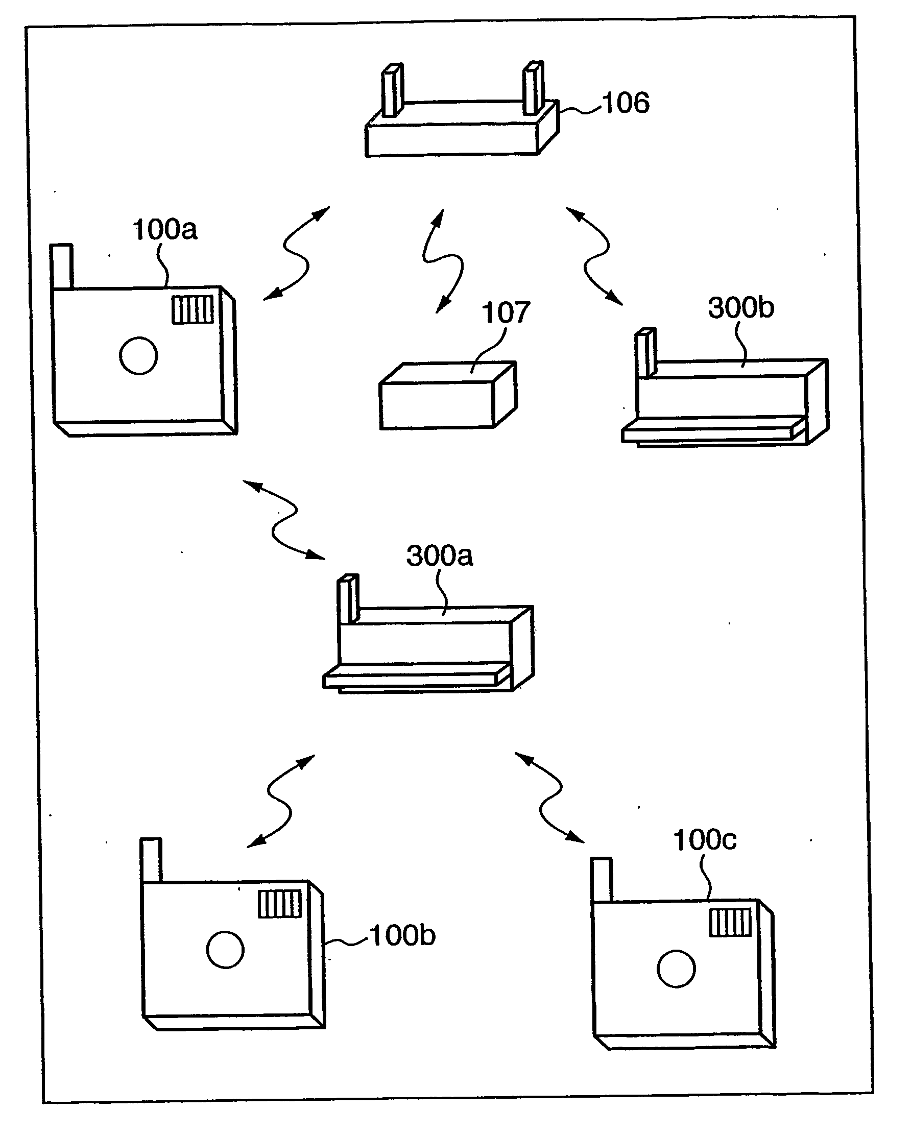
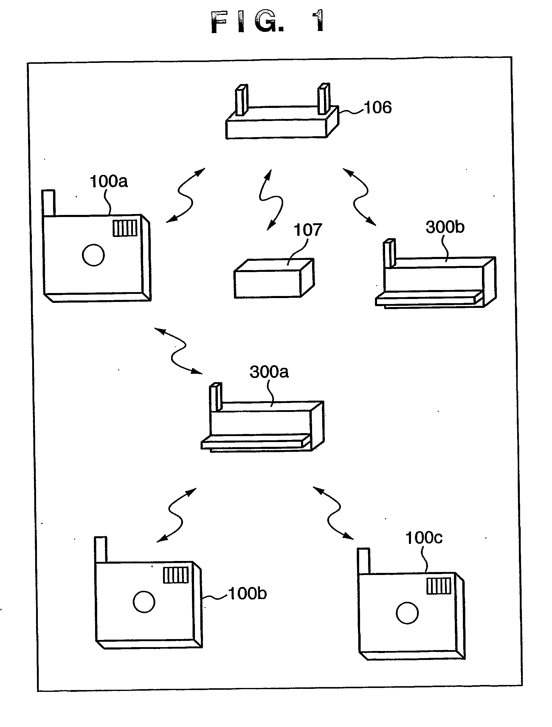
[0039]FIG. 1 is a block diagram showing the overall arrangement of a wireless communication system in this embodiment.

[0040] Referring to FIG. 1, reference numerals 100a to 100c denote digital cameras which serve as communication devices on the information transmitting side having wireless communication means. Reference numerals 300a and 300b denote printers which serve as communication devices on the information receiving side having wireless communication means. Reference numeral 107 denotes a storage device which serves as a communication device on the information receiving side having wireless communication means.

[0041] The digital cameras 100a to 100c can make data communications using the wireless communication means among themselves or with the printers 300a and 300b and the storage device 107 via an acce...

second embodiment

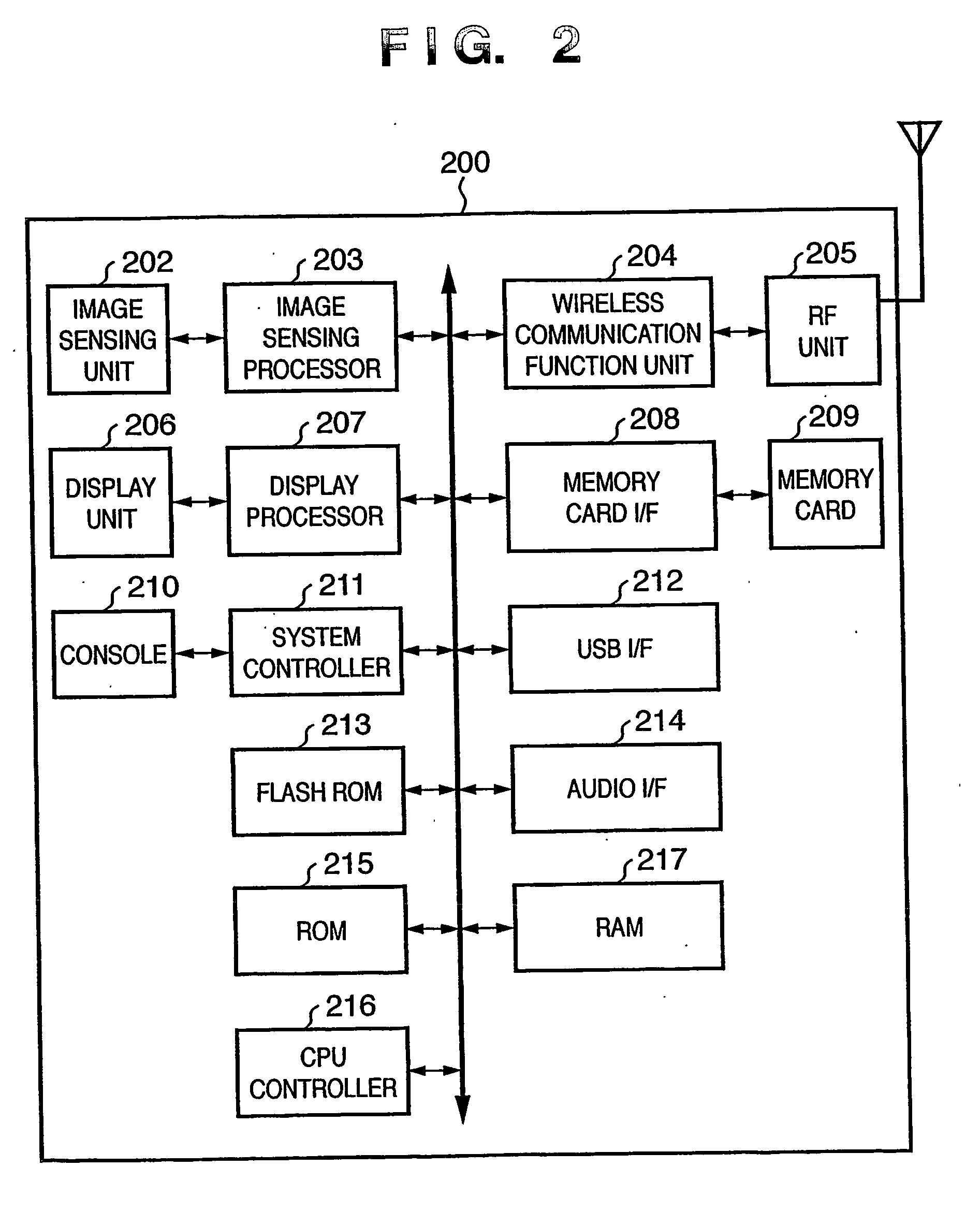
[0074] The second embodiment of the present invention will be described below. In the second embodiment, the detailed operation of the digital camera 200 which has a history search mode that searches history for a device to communicate with (without any wireless communication for the search process in practice), and a new search mode that searches for a new device will be described below using the flow chart of FIGS. 10A to 10C.

[0075] Upon operation of a device search instruction button (one of history search and new search buttons) of the digital camera, the number m of pieces of already stored history information (device identification information, SSIDs, and the like) is set, counter i indicating an index of a device information table stored in a history information storage area is reset to 0 (zero), and history information such as identification information, SSID at that time, and the like of each previously connected device (printer or storage), which is stored in the flash RO...

third embodiment

[0090] The third embodiment will be described below. The third embodiment will explain a case wherein identical network identification information (SSID) is set in both the two wireless communication devices, i.e., the digital camera 200 and printer 300.

[0091] The operation of the digital camera 200 in this embodiment will be described first with reference to the flow chart of FIG. 12.

[0092] Upon detection of an operation of a predetermined button that instructs to start a wireless communication process, it is checked if network identification information has already been set and registered in the flash ROM (step S1200). If no network identification information is set, a warning message “network setup information is not available” or the like is displayed (step S1203), thus ending this process.

[0093] If it is determined that network identification information has already been set and registered, it is checked if the communication mode of the set information is an adhoc mode (step...


PUM


Abstract

This invention has as its object to establish a wireless communication between wireless communication devices and to provide a desired service without any troublesome setup operations. To this end, a digital camera and printer of this invention have wireless communication functions. When it is determined that a wireless communication instruction is issued by a console of the digital camera, a beacon from a network is detected. Upon detection of the beacon, search request information used to confirm the presence of a wireless communication processing device on a network identified by network identification information included in the beacon is transmitted in accordance with that network identification information. If response information to this transmitted request information is detected, identification information of a partner wireless communication device included in the response information is stored, and is displayed to allow the user to select a connection target device.

Description

TECHNICAL FIELD [0001] The present invention relates to a communication establishment technique between devices having wireless communication functions. BACKGROUND ART [0002] Normally, a host computer as a versatile information processing apparatus such as a personal computer or the like and a printer are connected by wire. Such wired connection adopts a USB cable, parallel cable (complying with the Centronics standards (USA)), Ethernet®, and the like. [0003] In recent years, digital cameras have prevailed increasingly, and the recording quality of printers has improved as high as silver halide photos. Hence, there are many chances of printing images sensed by such digital camera by printers. [0004] In order to print an image sensed by a digital camera, it is a common practice to transfer that image to a personal computer, and to print it by operating an application program that runs on the personal computer. [0005] However, a digital camera user requires a personal computer when he...

Claims


Application Information

Patent Timeline
Patent Type & Authority Applications(United States)
IPC IPC(8): H04L12/28H04W48/14H04W48/16
CPCH04W48/14H04W48/16H04W84/18H04W88/02H04W8/20
Inventor FUJII, KEN'ICHIWATANABE, MITSUHIRONAKAHARA, MASANORI
Owner CANON KK
Learn More