Portable vehicle canopy

a technology for vehicles and canopy covers, applied in the field of canopy covers, can solve the problems of poor functionality, poor sun protection, and poor functionality of the operator of a riding lawn mower, and achieve the effect of quick and easy removal

Inactive Publication Date: 2007-08-14
MILNER CHARLES EDWARD +1
View PDF23 Cites 13 Cited by
  • Summary
  • Abstract
  • Description
  • Claims
  • Application Information

AI Technical Summary

Benefits of technology

[0011]In accordance with the present invention, there is provided a portable vehicle canopy that is both functional and stylish. A curved tubular frame work supports a nylon shade material. Hold down straps use common hardware for attachment to riding lawn mower.

Problems solved by technology

The operator of a riding lawn mower has little to none protection from the sun's ray and the heat.
With any outdoor vehicle, protection from the sun's ultraviolet rays has always been a challenge.
Vehicle shade canopies have been designed and produced but most are overcomplicated resulting in poor functionality.
Other canopy designs are hard to assemble, require tools, modification for the mower itself, and do not provide for easy access for the operator to get in the seat, for example, in U.S. Pat. No. 6,059,351.
Most people are not willing to drill holes in the fenders and hood of their riding lawn mower to mount a canopy.
Also, current canopies are not easily or quickly removable for storage or while mowing under low hanging limbs.

Method used


Image

  • Portable vehicle canopy
  • Portable vehicle canopy
  • Portable vehicle canopy

Examples


Embodiment Construction

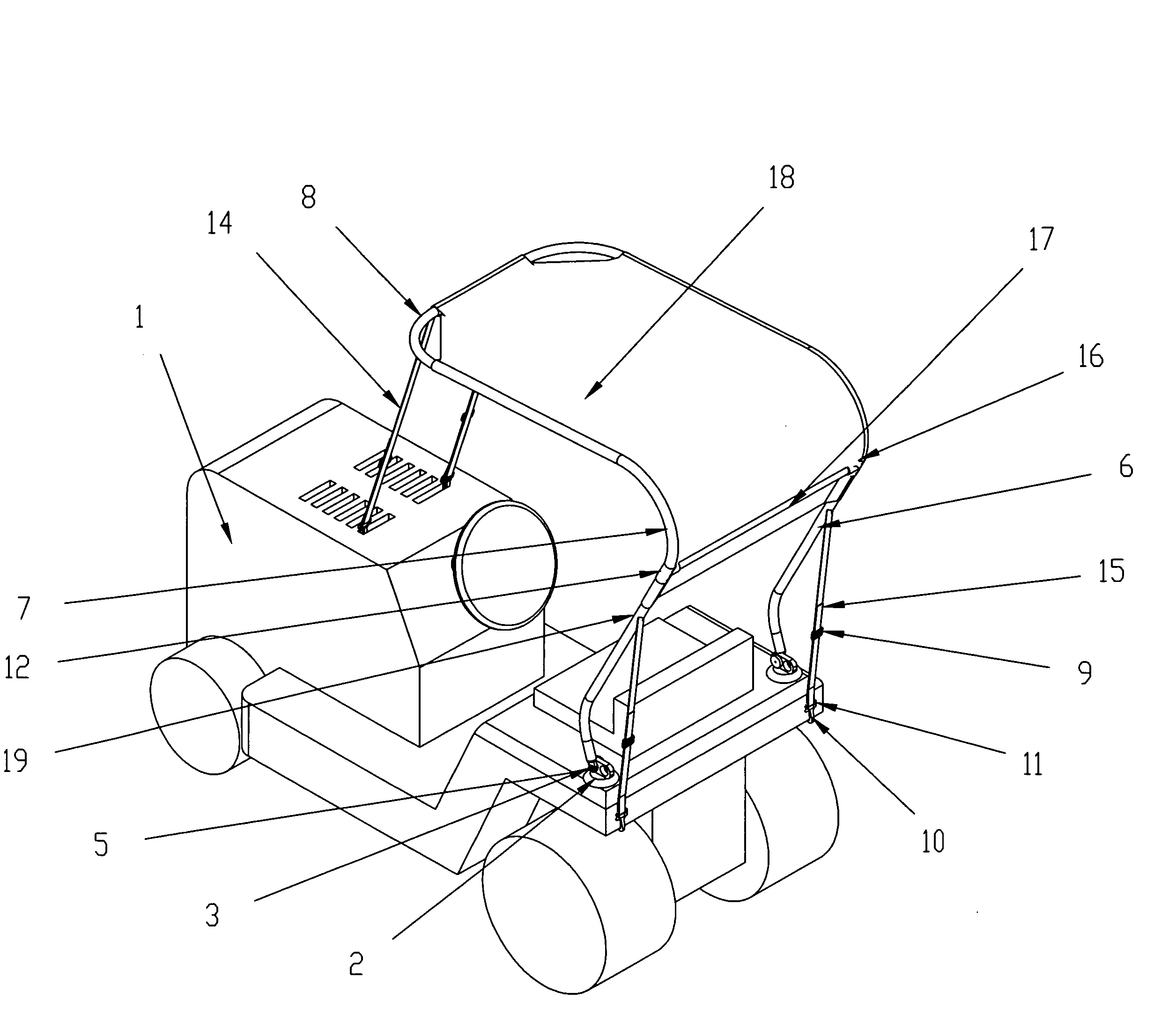
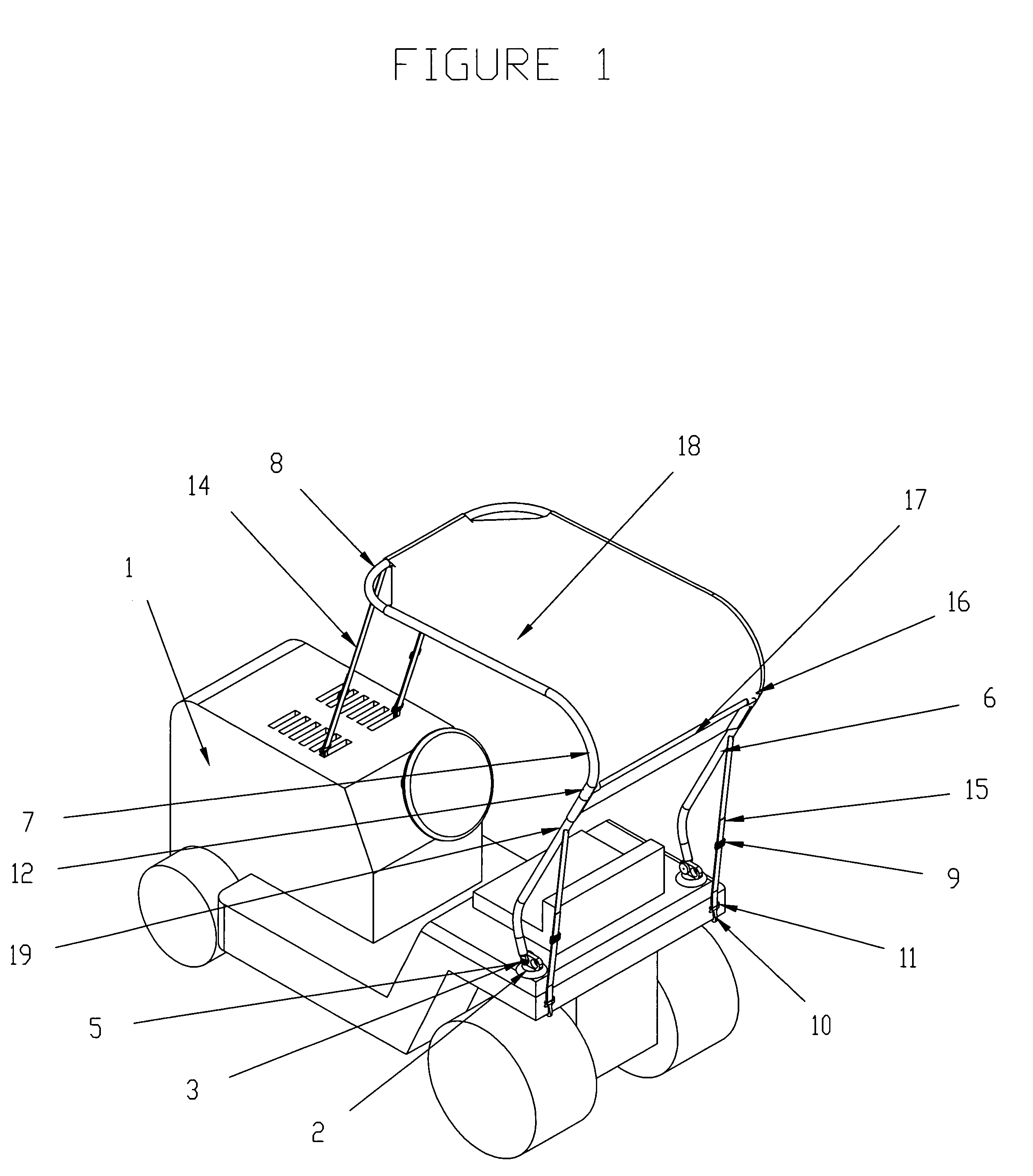
[0017]FIG. 1 is a perspective view of a Portable Vehicle Canopy mounted on a typical Riding Lawn Mower 1. The portable vehicle canopy apparatus is provided for a Riding Lawn Mower 1 (vehicle). A pair of Suction Cup 2 attaches to the painted fender surface of Riding Lawn Mower 1 (vehicle). Two Bushing 4 are mounted into the pair of Suction Cup 2 to provide pivotal motion of the canopy framework. Each Eye End 5 is fastened to Bushing 4 by means of Shoulder Screw 3. The Eye End 5 is mounted non-removable to the Upright Tube 6. Two Upright Tube 6 are included in the assembly. The Upright Tube 6 connects to the Top Tube 7 by means of the Tube Coupling 12 and the Spring Clip Fastener 19. Two Top Tube 7 are included in the assembly. Each Top Tube 7 connects to the Front Tube 8 by means of the Tube Coupling 12 and the Spring Clip Fastener 19. The T-Bracket 16 and Spring Clip Fastener 19 mounts the Back Tube 17 across to the two Top Tube 7 setting the width and providing a structural cross m...


PUM


Abstract

A universal portable vehicle canopy unit is provided for a front engine riding lawn mower style vehicle and includes suction cup affixing to the rear fender for easy assembly and disassembly of unit to vehicle. The portable vehicle canopy is supported by two vertical upright tube assemblies that are pivotally connected to the vehicle. Front and back of the canopy framework is held upright by adjustable length straps. A flexible canopy sheet assembly constructed of light weight nylon or similar materials is supported by the top canopy framework cross beams. Main usage for the portable vehicle canopy would be protection from sun light. Secondary usage for the portable vehicle canopy would be to ward off light rain. Material of the canopy frame work structure is light guage aluminum bent tubing or plastic molded tubing.

Description

FIELD OF THE INVENTION[0001]The current invention relates to canopies and, more particularly, the protection from the sun's ultraviolet rays for the riding lawn mower operator.BACKGROUND OF THE INVENTION[0002]The operator of a riding lawn mower has little to none protection from the sun's ray and the heat. With any outdoor vehicle, protection from the sun's ultraviolet rays has always been a challenge.[0003]Vehicle shade canopies have been designed and produced but most are overcomplicated resulting in poor functionality. Other canopy designs are hard to assemble, require tools, modification for the mower itself, and do not provide for easy access for the operator to get in the seat, for example, in U.S. Pat. No. 6,059,351. Some mower canopy designs use the implement hitch on the mower so it cannot be used while the canopy is installed on the mower; see U.S. Pat. No. 5,232,005.[0004]Model specific mower canopies are available but, will only work on the specified mower model. Mower c...

Claims


Application Information

Patent Timeline
Patent Type & Authority Patents(United States)
IPC IPC(8): E04H15/06A01D34/81
CPCA01D34/81
Inventor MILNER, CHARLES EDWARDMALOTT, MICHAEL LEE
Owner MILNER CHARLES EDWARD
Why Eureka
Try Eureka