Fluid pressure system including free floating bladder

a technology of fluid pressure system and floating bladder, which is applied in the direction of service pipe system, borehole/well accessories, transportation and packaging, etc., can solve the problems of difficult installation, high cost, and most of the problems of prior art system, and achieve the effect of convenient and secure installation, cost-effectiveness

Active Publication Date: 2007-08-14
IN WELL TECH
View PDF49 Cites 5 Cited by
  • Summary
  • Abstract
  • Description
  • Claims
  • Application Information

AI Technical Summary

Benefits of technology

[0018]The present invention provides a bladder that is cost-effective, easily and securely fitted to a fluid pressure system, provides control of the amount and pressure of fluid flowing through and out of the fluid system, and solves the problems raised by existing prior art designs.

Problems solved by technology

However, most of these prior art systems suffer from serious flaws.
Most require a tank that includes a number of parts, is difficult to install, and is expensive.

Method used


Image

  • Fluid pressure system including free floating bladder
  • Fluid pressure system including free floating bladder
  • Fluid pressure system including free floating bladder

Examples


Embodiment Construction

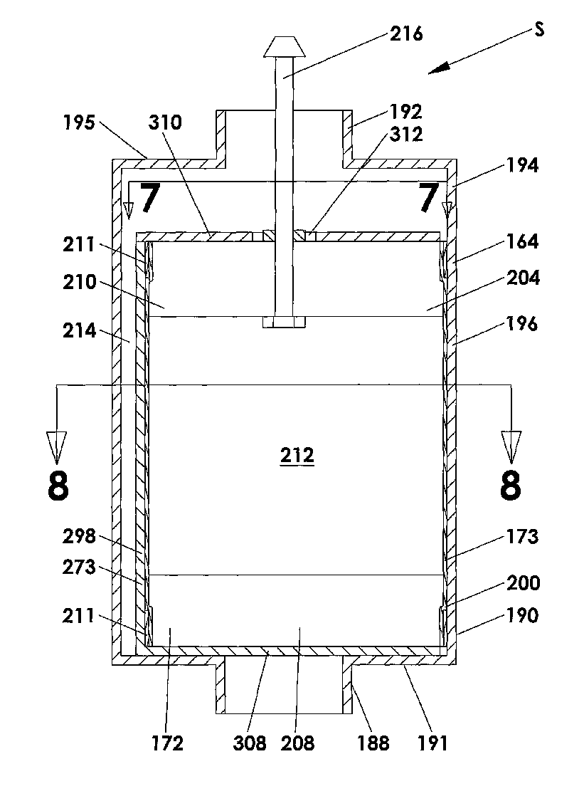
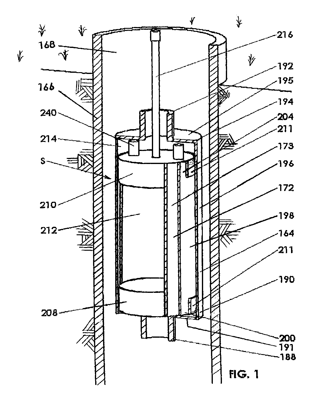
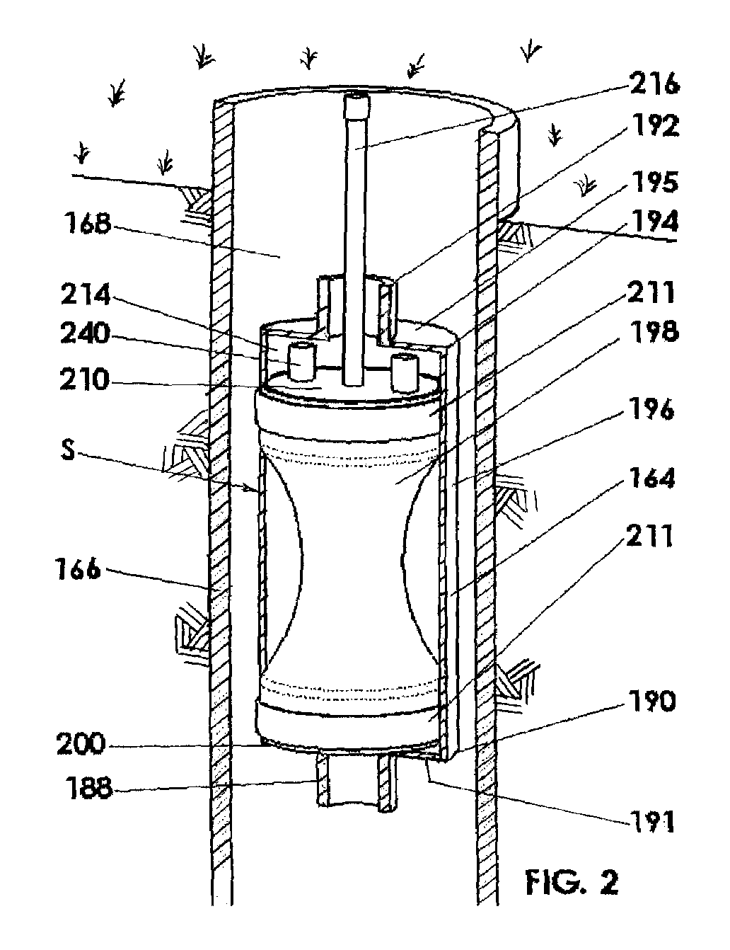
[0033]The present invention comprises a bladder installed within a fluid system to control the pressure of fluid in the fluid system. Changes in the volume of the bladder inversely impact the amount of fluid expansion or the amount of fluid stored in the system. Specifically, a larger bladder volume results in less fluid or gas storage or expansion and a smaller bladder volume results in more fluid or gas storage or expansion. The bladder is preferably free floating in the fluid system with some mechanism to keep it somewhat in place as fluid passes or flows around it. The fluid preferably encompasses the bladder of the fluid pressure system. The bladder is preferably restricted to a maximum cross sectional size, which is preferably less than the cross sectional size of the fluid system where it is installed.

[0034]The fluid pressure system stores fluid, controls fluid expansion due to pressure or temperature changes, controls and adjusts pressure by smoothing out highs and lows of p...


PUM


Abstract

A fluid pressure system (S) includes a flexible diaphragm bladder (172) located inside a pressure tank (164) installed within a fluid system such as well (168). In preferred aspects, the bladder (172) can be inflated by the introduction of air and is located within a flexible confining tube (198) or confining element (298) for preventing over expansion of the bladder (172). The bladder (172) and the confining tube or element (198, 298) are free floating in and without physical connection with the pressure tank (164) in preferred forms. The pressure tank (164) includes a flexible side wall (196) to allow folding or willing of the assembled fluid pressure system (S) in preferred forms. Confining tube (198) in a preferred form is of a cylindrical configuration and arranged concentrically around the bladder (172). Confining element (298) is carried by the bladder (172) and creates a barrier extending along a chord of a cross section of pressure tank (164).

Description

CROSS REFERENCE[0001]This application is a continuation-in-part of U.S. application Ser. No. 10 / 990,618 filed on Nov. 17, 2004, now U.S. Pat. No. 7,013,924, which claims the benefit of U.S. Application No. 60 / 495,588 filed on Nov. 17, 2003.BACKGROUND AND SUMMARY OF THE INVENTION[0002]The present invention relates generally to a fluid pressure system. Specifically, this invention relates to a free floating bladder inserted within a fluid pressure system to store liquid or gas in the system, control liquid or gas expansion due to pressure or temperature changes, and control pressure, including pressure spikes, in the system by damping pressure changes.[0003]Storing and controlling the flow of fluids such as liquids or gas and absorbing pressure changes within a fluid pressure system are important in many different situations. For example, pressure control systems are utilized in connection with wells. Commercial buildings, residential buildings and municipal water systems are often eq...

Claims


Application Information

Patent Timeline
Patent Type & Authority Patents(United States)
IPC IPC(8): F16L55/04
CPCF16L55/04E03B7/003
Inventor MEYERS, KENNETH A.MOON, THOMAS A.
Owner IN WELL TECH
Why Eureka
Try Eureka