Immobilizing and supporting inflatable splint apparatus

a splint and inflatable technology, applied in the field of medical devices, can solve the problems of limiting the application of the device, affecting the safety of the patient, and the device suffers from inconvenient structure, so as to minimize the overall discomfort, facilitate and secure the fit of the injured, and maximize the adjustment range

Active Publication Date: 2005-09-15
R & D SUPPORTS
View PDF16 Cites 18 Cited by
  • Summary
  • Abstract
  • Description
  • Claims
  • Application Information

AI Technical Summary

Benefits of technology

[0009] In accordance with the shortcomings of previous art, it is a principal object of the present invention to provide a splint device which will present a maximum adjustment range, so it can be easily and securely fitted to the injured body part, without bringing about any uncomfortable chafing and minimize the overall discomfort, will also allow for adequate blood circulation to the injured part, and support the joints in an optimal position with a controllable measure of rigidity.

Problems solved by technology

The main drawback of the device, which limits its application considerably, relates to its fixed and inflexible shape that does not take into consideration the rounded form of the limbs, joints and the torso, for instance.
As in the previous patent, this device suffers from an inconvenient structure, which may only support the calf, the ankle and the foot of a patient without conforming to the shape of these structures.

Method used


Image

  • Immobilizing and supporting inflatable splint apparatus
  • Immobilizing and supporting inflatable splint apparatus
  • Immobilizing and supporting inflatable splint apparatus

Examples


first embodiment

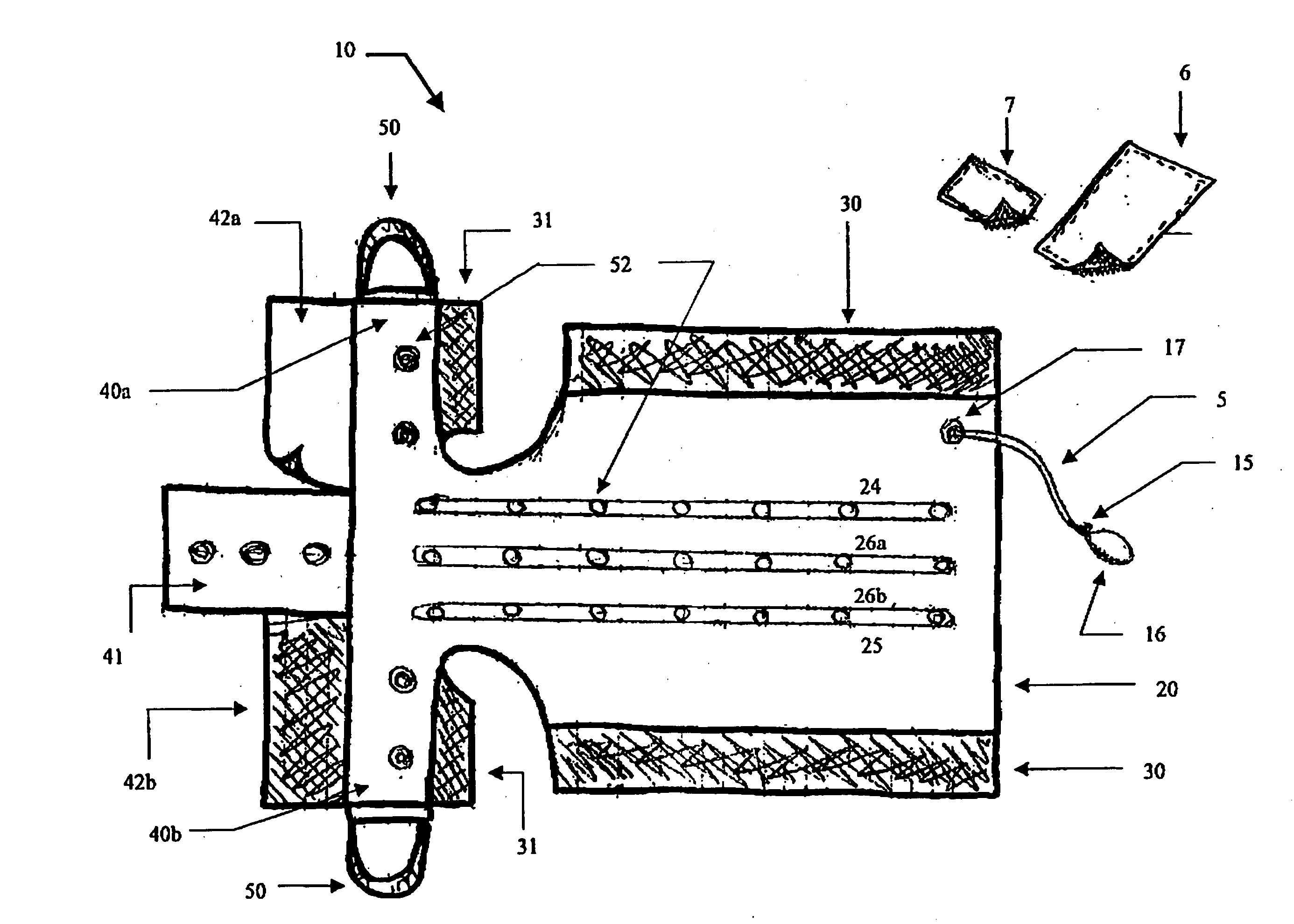
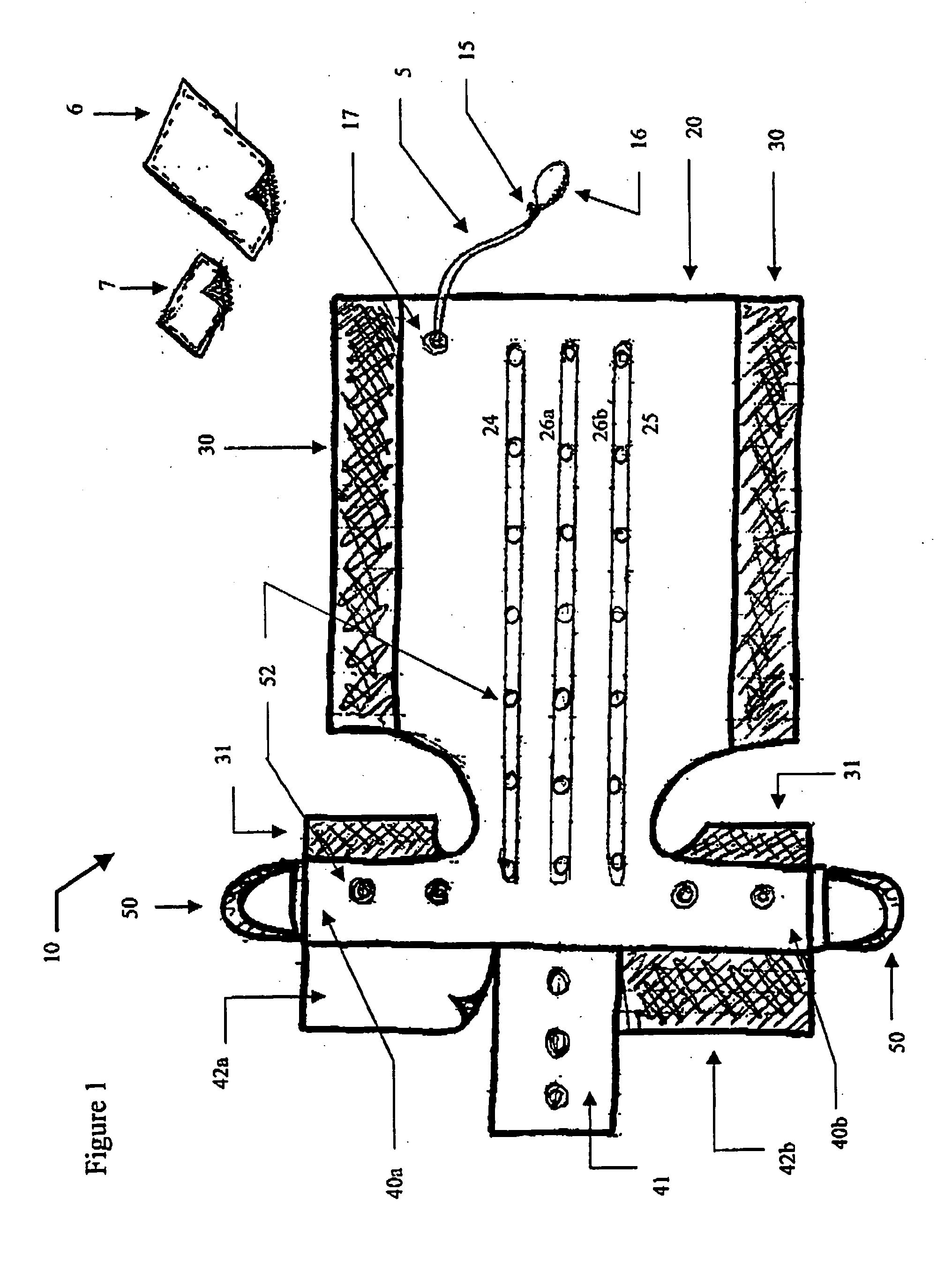
[0024]FIG. 1 offers a general description of the invention, suited for leg injuries, in an unassembled condition. The splint 10 is comprised of a main body 20 and two or more unattached adjustable straps: an front upper strap 6 and a front lower strap 7. When in use, parts 24, 25, 26a, 26b wrap the leg from three sides: part 24 holds the left side of the leg and part 25 the right side, while the back of the leg is wrapped by the splint central part 26a, 26b. Connecting Velcro surfaces 30 and 6 fastens the device around the calf.

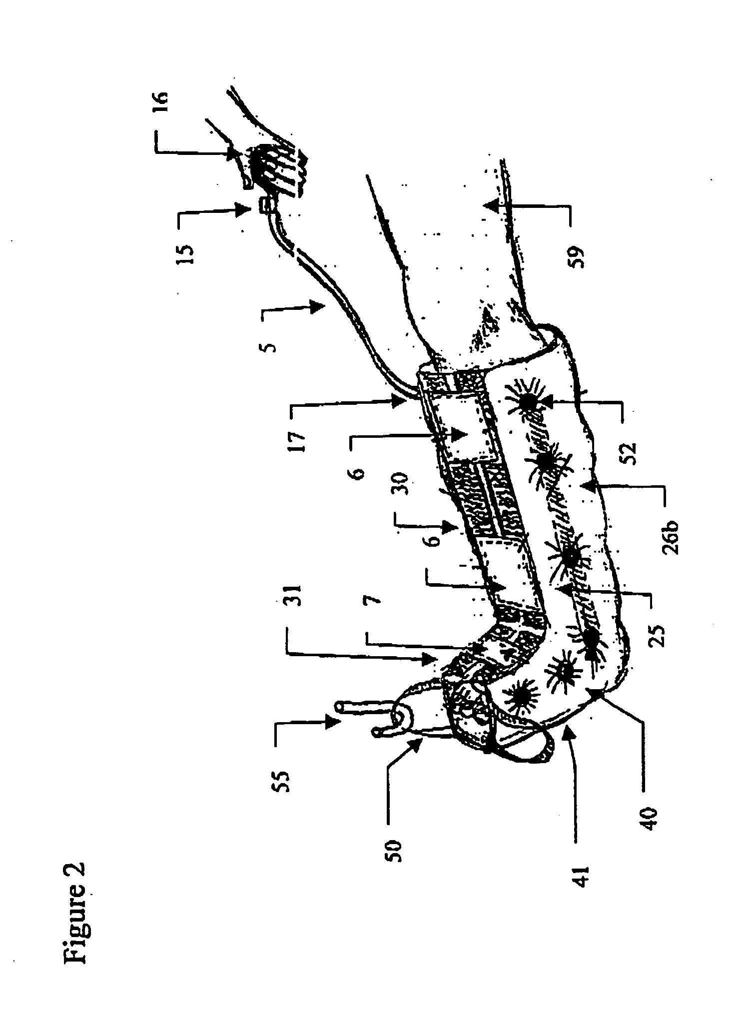
[0025] The lower right 40a and left part 40b of the splint wraps around the foot, while part 41 covers the sole of the foot. Attaching Velcro straps 31 to strap 7 on top of the foot and strap 42a to 42b at the sole fastens the lower part of the splint for supporting the lower part of the foot. FIG. 2 illustrates the device as it is assembled on a leg 59.

[0026] Both the lower and the upper part of the splint have ventilating holes 52 to increase the comfort o...

second embodiment

[0030]FIG. 3 illustrates the second embodiment in an unassembled state. The main body of the splint is divided into two parts: for supporting the upper part of the arm 61a (between the shoulder and the elbow) and of the lower part of the arm 61b (between the elbow and the wrists). Enclosing the main body 61 are Velcro straps 62, 63 which connect to each other when the device is assemble on an arm. The main part 61a contains an aperture for the shoulder 67 and the main part 61b includes an aperture for the palm 66 and a supporting surface for the palm and hand 65.

[0031] Like the main body of the first embodiment these two sections are both comprised of inflatable tubes which, when assembled on the arm, are designed to support the arm from three directions. FIG. 4 displays a cross-section of the splint when it is inflated and unassembled. This figure clearly shows the four tubes in the splint Velcro straps 62, 63 connect when the splint is assembled.

[0032] Also in FIG. 3 are the vent...


PUM


Abstract

Disclosed is a medical device which operates as a supporting splint for the treatment of orthopedic conditions. Said device is an inflatable, flexible, lightweight water-resistant splint whose measure of rigidity is easily controlled by the user. According to the present invention there are several embodiments of the splint, each suited to fit a different body part such as the limbs, the torso, the chest and the neck. Said device which is constructed of inflatable tubes is made of two nylon layers soldered together and is coated with polyurethane. The tubes may be inflated by an attachable hand pump or by other means of supplying air pressure. The present invention is especially designed to allow the normal blood circulation to the treated body part, provide ventilation to the area and enable easy inspection of an injury.

Description

FIELD OF THE INVENTION [0001] The present invention relates to the field of medical devices, and, more particularly, it relates to inflatable versatile / universal multi purpose splints. BACKGROUND OF THE INVENTION [0002] The traditional techniques of providing support and immobilization in orthopedic conditions revolves around three types of devices: casts, which have application primarily in broken limbs; splints, which are used to immobilize and stabilize the limbs and the torso; and pressure bandages, which help control swelling and give a degree of support. [0003] Creative individuals have come up with a variety of departures from these standard themes in order to achieve better patient treatment. Inflatable pouches made from elastic materials exist, adapted to be filed with either liquid or gas, and incorporating means for securing these pouches to the injured part of a human body and tightening them around it. Splints of this kind effect the immobilization and compression of a ...

Claims


Application Information

Patent Timeline
Patent Type & Authority Applications(United States)
IPC IPC(8): A61F5/00
CPCA61F5/05816
Inventor REIS, DANIELZUCKER, DALIANUN, ASHER BIN
Owner R & D SUPPORTS
Why Eureka
Try Eureka