Hinge device

a technology of a hinge and a handle, which is applied in the direction of portable computer details, instruments, manufacturing tools, etc., can solve the problems of hard wear and durability after long time of operation, and achieve the effect of hard wear and durability

Inactive Publication Date: 2007-08-21
HORNG CHIN HSING
View PDF16 Cites 15 Cited by
  • Summary
  • Abstract
  • Description
  • Claims
  • Application Information

AI Technical Summary

Benefits of technology

[0006]In view of the described inconvenience and drawbacks, the applicant of the invention herein researched and developed a hinge which has larger value of torque; meanwhile, it's easy to produce a hinge device having different values of torque. The objective of the invention herein is to provide a kind of endurable and hard-wearing hinge device such that a decrease in torque will not occur after being used for a long time. In addition, the present invention can be fitted on more products and it has a sense of excellence for better exterior design.
[0008]A curved portion is formed at both sides of the liner portion body and liner member body respectively such that the liner tube, either in a configuration by aligning at least two liner portions or by means of one liner member, is fixed in the passage of the cylindrical body and then the shaft portion of the rotating shaft is pivotally inserted into the hole of the liner tube so that the assemblage of the present invention is complete. As such, between the curved portion and the cylindrical body is left some space for expansion in the state that the liner portion body or liner member body is not tightly bound with the cylindrical body. When the shaft portion of the rotating shaft inset through the hole of the liner tube turns clockwise or counterclockwise, the rotation of the present invention is made in a smooth manner which further results in hard wear and durability after operation for a long time.

Problems solved by technology

When the shaft portion of the rotating shaft inset through the hole of the liner tube turns clockwise or counterclockwise, the rotation of the present invention is made in a smooth manner which further results in hard wear and durability after operation for a long time.

Method used


Image

  • Hinge device
  • Hinge device
  • Hinge device

Examples


Embodiment Construction

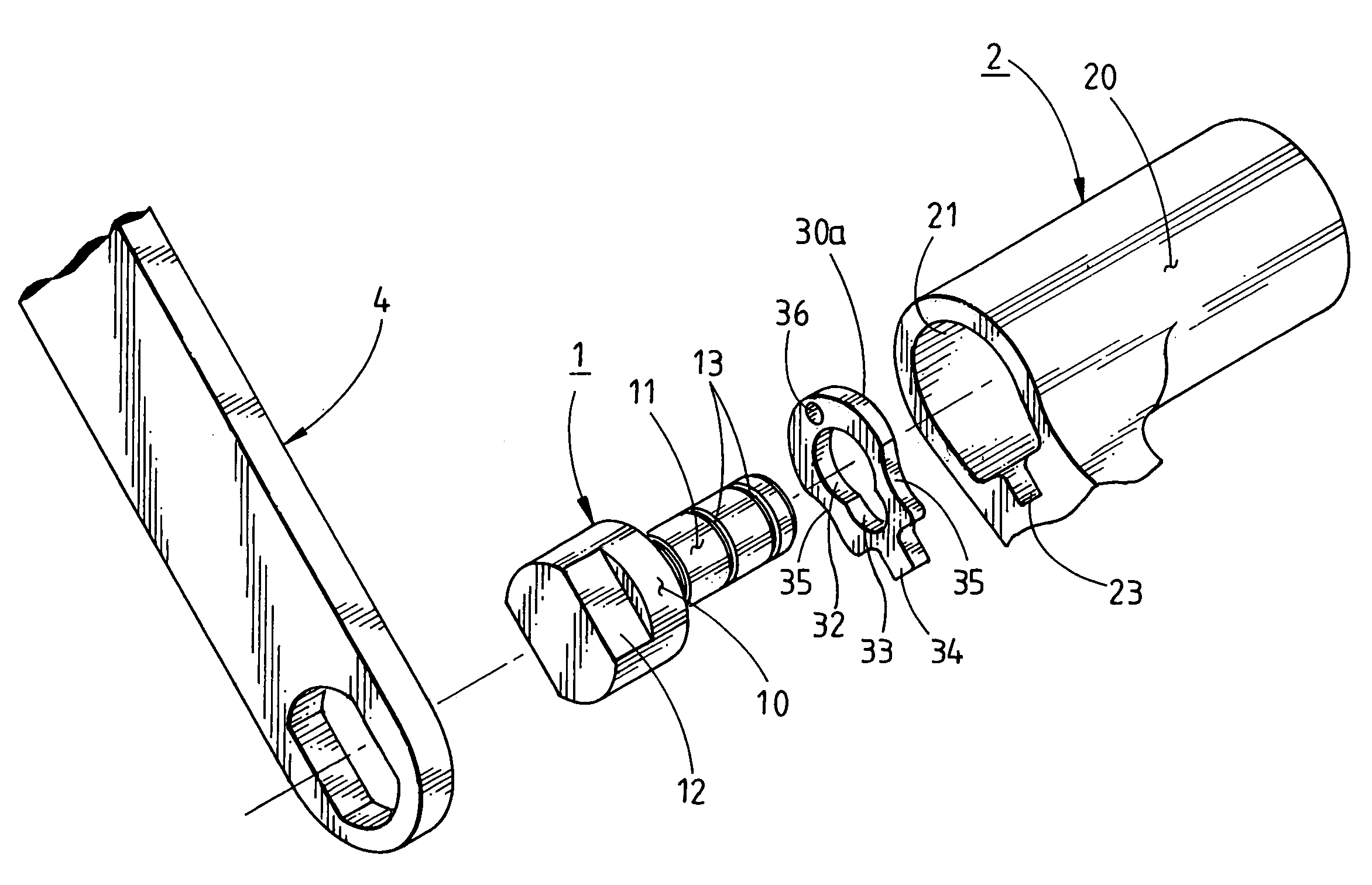
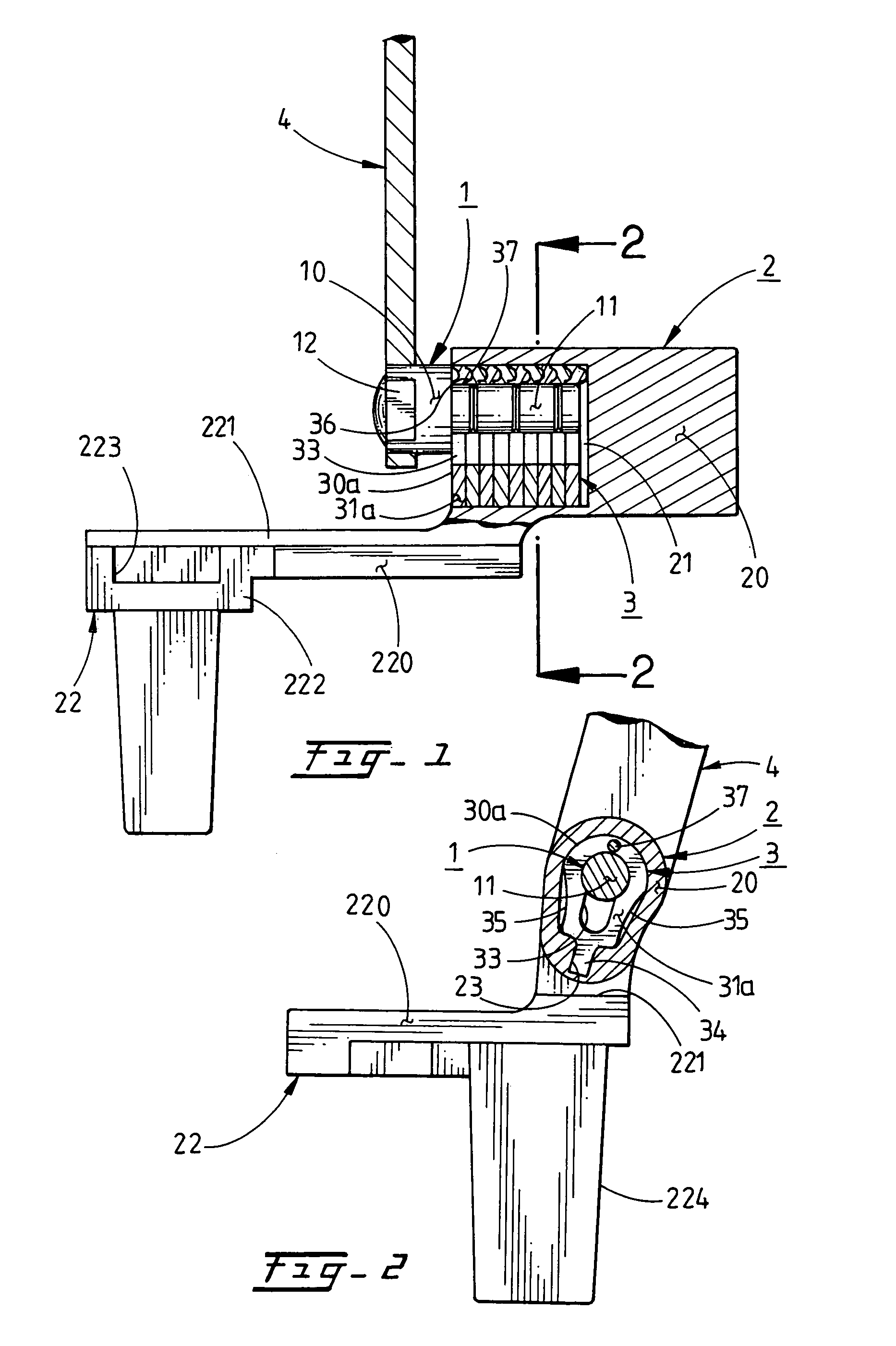
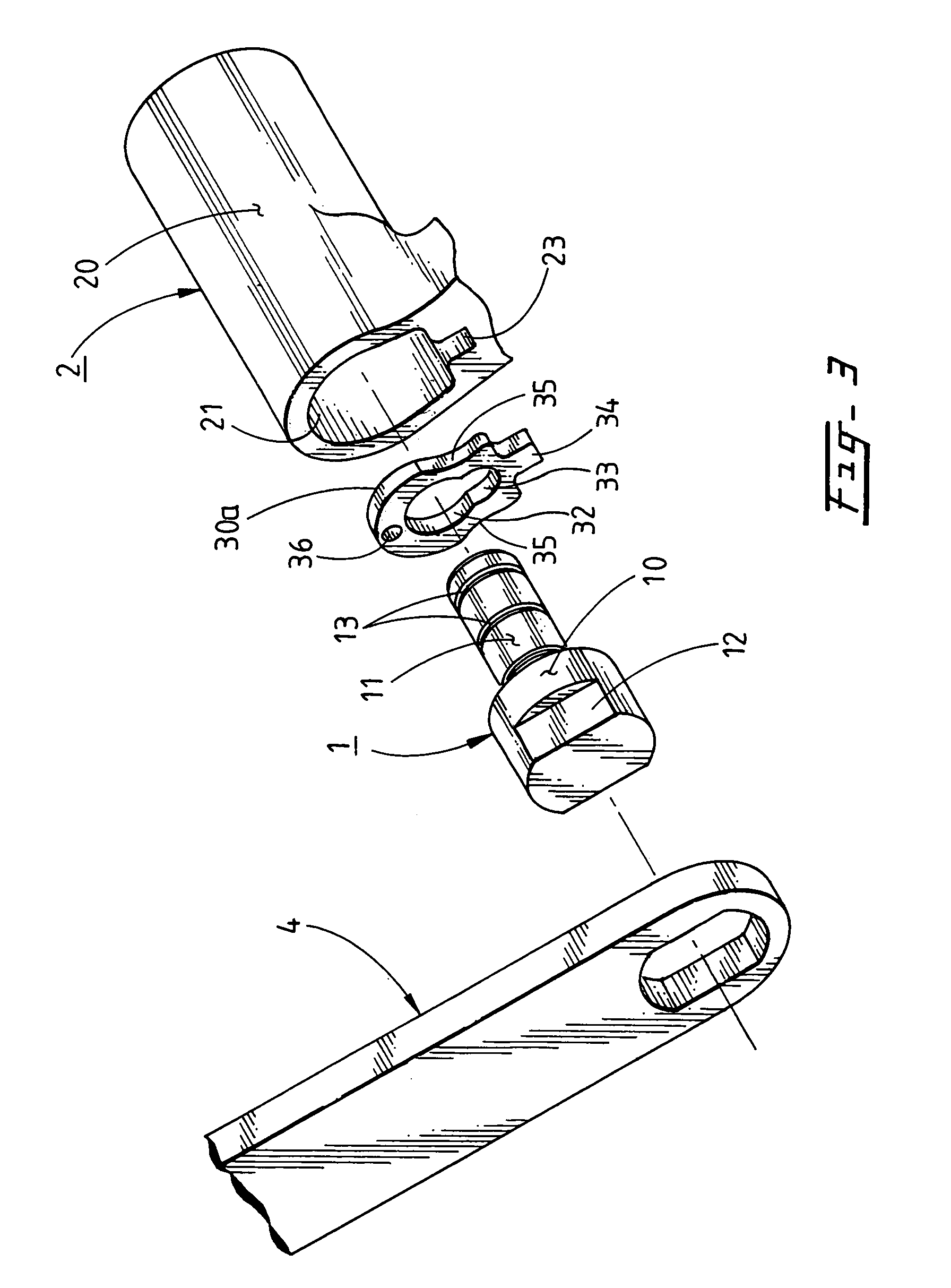
[0020]Referring to FIG. 1, FIG. 2 and FIG. 3, the hinge device of the present invention includes a rotating shaft 1, a cylinder 2 and a liner tube 3. Each of the components and the embodiment of the present invention will be described in detail below, as shown in FIG. 3. The rotating shaft 1 consists of a joint portion 10, a shaft portion 11 and an affixing portion 12. Along the outer periphery of the shaft portion 11 is formed at least one guiding groove 13. The cylinder 2 has a cylindrical body 20, an oval passage 21 inside the cylindrical body 20 and a fixing member 22 extending from one side thereof (see FIGS. 1 and 2.) A positioning groove 23 is arranged at the lower end of the passage 21 for pivotal connection with a liner tube 3, as shown in FIG. 2.

[0021]The liner tube 3 comprises two or more pieces of liner portion 30a with a hole 32 therein, and each of the liner portions 30a is combined in alignment, as illustrated in FIG. 1; alternatively, the liner tube 3 comprises a lin...


PUM


Abstract

The hinge device comprises a rotating shaft, a cylinder and a liner tube. The cylinder contains a cylindrical body having a passage therein, a fixing member and a positioning groove. The liner tube includes at least two pieces of liner portion with a hole therein, or it includes a liner member having a hole therethrough. A positioning flange is projected on the end of the liner tube so as to engage with the positioning groove. At both sides of the liner tube are formed curved portions respectively. While a shaft portion of the rotating shaft is pivotally inserted into the hole, between the curved portion and the cylindrical body is left some space for expansion; therefore, as the rotating shaft turns clockwise or counterclockwise, the rotation of the present invention is made smoothly which further results in hard wear and durability.

Description

BACKGROUND OF THE INVENTION[0001]1. Field of the Invention[0002]The invention herein relates to a hinge device having the advantages of simple structure and easy assemblage, and specifically, it is convenient to manufacture a hinge device whose torque differs in the defined condition, wherein a torque of the present invention is relatively bigger depending on the rotational direction or upward / downward movement. When the hinge device is in use, it enables to maintain the same torque since it is quite endurable and hard-wearing, thereby preventing its torque from decreasing after long-term usage. Moreover, the present invention can be fitted with more electric products and it has a sense of excellence for better exterior design.[0003]2. Description of the Prior Art[0004]The present invention is in reference to Taiwan Patent Bulletin Patent No. 092,219,622, which claimed further improvement to the related art.[0005]The prior hinge consists of a revolvable shaft, a fixed plate or brack...

Claims


Application Information

Patent Timeline
Patent Type & Authority Patents(United States)
IPC IPC(8): E05D11/08E05D7/00E05D5/12E05D5/14F16C11/04G06F1/16H05K7/16
CPCE05D5/12E05D5/14E05D11/084G06F1/1616G06F1/1681E05D11/087Y10T16/529Y10T16/54038E05Y2900/606
Inventor HORNG, CHIN-HSING
Owner HORNG CHIN HSING
Why Eureka
Try Eureka