Image heating apparatus with heating nip for preventing image failure

a technology of heating apparatus and heating nip, which is applied in the direction of electrographic process apparatus, instruments, optics, etc., can solve the problems of large heat capacity, low glossiness, energy conservation, etc., and achieve the effect of less pressure releas

Active Publication Date: 2007-08-21
CANON KK
View PDF11 Cites 10 Cited by
  • Summary
  • Abstract
  • Description
  • Claims
  • Application Information

AI Technical Summary

Benefits of technology

[0020]The present invention has another object to provide an image heating apparatus in which less pressure release occurs in a heating nip.

Problems solved by technology

A nip width W3 of the roller fixing type fixing apparatus is somewhat wider than the nip width W2 as shown in the curve B. However, an effect obtained by enlarging the nip width is small, and in addition, the thick elastic member layer causes a heat capacity to be large, which is disadvantageous in view of energy conservation.
In the belt fixing apparatus, however, when a recording material, such as a coated paper sheet, having a low air permeability is used, there is another problem in that a portion in which the glossiness is low (haze: hereinafter referred to as uneven glossiness), as shown in FIG. 11, is formed in an icicle-like shape on a solid image.
In other words, in a case where the recording material having a low air permeability such as a coated paper sheet is used, an image disturbance occurs due to an expansion of air or generation of steam inside the fixing nip.
Further, in the case of a recording material having an especially low air permeability such as a thick coated paper sheet, a larger amount of air is likely to be stagnated in the portion A′ in which the pressure is decreased.
Therefore, the problem of occurrence of the uneven glossiness described above becomes more serious.
Note that under an environment of high humidity in which the air contains high moisture content, the problem like this noticeably occurs.

Method used


Image

  • Image heating apparatus with heating nip for preventing image failure
  • Image heating apparatus with heating nip for preventing image failure
  • Image heating apparatus with heating nip for preventing image failure

Examples


first embodiment

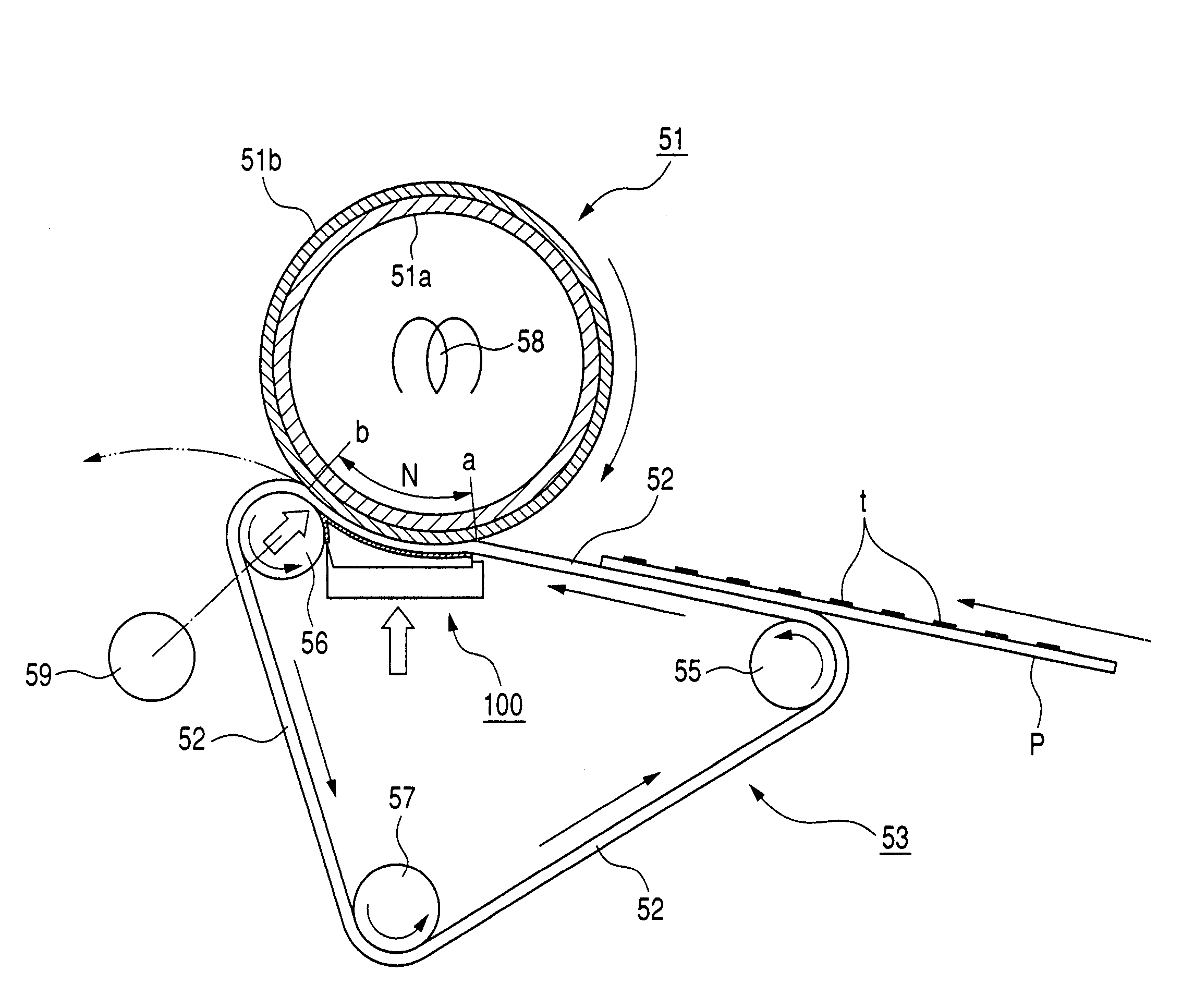
[0036]FIG. 3 is an outline configuration diagram of a belt fixing apparatus, which is an image heating apparatus of this embodiment.

[0037]A fixing roller 51 which is a heat rotary member (fixing rotary member) is configured to have a metal core 51a made of Fe which has an inner diameter of φ37.8 mm, an outer diameter of φ38.4 mm, and a thickness of 0.3 mm. As an elastic layer 51b, a silicone rubber layer having a thickness of 0.5 mm is formed on the metal core 51a. A PFA tube having a thickness of 30 μm which is a releasing layer covers the elastic layer 51b. As a result, the fixing roller has the outer diameter of 40 mm.

[0038]A fixing belt 52, which is an endless belt, has a base layer of a thickness of 100 μm made of polyimide. The silicone rubber layer having a thickness of 0.2 mm covers the base layer. As a result, the outer diameter of the fixing belt 52 is φ90 mm. Note that the fixing belt of this embodiment is a seamless belt.

[0039]The fixing belt 52 is looped around three ro...

second embodiment

[0092]In a second embodiment of the present invention, a method of covering with the sliding sheet 103 is as shown in FIG. 7A. That is, the covering with the sliding sheet 103 is carried out so that the filling ratio of S / S0 of the sliding sheet 103 is expressed by an expression

S / S0=0.80(S1 / S0=0.20).

Other configurations are the same as the configurations of the first embodiment.

[0093]When the fixing nip pressure distribution as described in the first embodiment is measured with the above configuration, the fixing nip pressure distribution as shown in FIG. 7B is observed. In this case, when the pressure between the position X1 and the position X2 is P(X), the minimum value Pmin(X) of P(X) is expressed by the expression

Pmin(X)=0.7×P(X1).

[0094]A comparative experiment as described below is carried out with the above configuration. For the fixing conditions, the surface temperature of the fixing roller 51 is controlled to 170° C. and the range of the surface temperature of the fixing be...

third embodiment

[0100]In a third embodiment of the present invention, a method of covering with the sliding sheet 103 is shown in FIG. 8A. That is, the covering with the sliding sheet 103 is carried out so that the filling ratio of S / S0 of the sliding sheet 103 is expressed by an expression

S / S0=0.85(S1 / S0=0.15).

Other configurations are the same as the configurations of the first embodiment.

[0101]When the fixing nip pressure distribution as described in the first embodiment is measured with the above configuration, the fixing nip pressure distribution as shown in FIG. 8B is observed. At this time, when the pressure between the position X1 and the position X2 is P(X), the minimum value Pmin(X) of P(X) is expressed by the expression

Pmin(X)=0.8×P(X1).

[0102]A comparative experiment as described below is carried out with the above configuration. For the fixing conditions, the surface temperature of the fixing roller 51 is controlled to 170° C. and the range of the surface temperature of the fixing belt 5...


PUM


Abstract

A belt nip type fixing apparatus, which prevents a formation of an icicle-like uneven glossiness occurring on a surface of a fixed image due to pressure release in a fixing nip. In addition, an image forming apparatus provided with the fixing apparatus for preventing an occurrence of image failure even in a case where a coated paper sheet, which is most likely to cause the image failure, is used as a recording material and for enlarging a scope of application of the recording material while maintaining a productivity, to thereby attain an improved merchantability. The apparatus is configured such that a wedge-shaped space, which is formed between a belt, a separation roller, and a pressure pad, is adequately filled by a sliding sheet, thereby preventing a pressure in the fixing nip from being decreased.

Description

BACKGROUND OF THE INVENTION[0001]1. Field of the Invention[0002]The present invention relates to an image heating apparatus for heating an image on a recording material, which is used for an image forming apparatus such as a copying machine, a printer, or a facsimile machine. Examples of the image heating apparatus include a fixing apparatus for fixing an unfixed image on a recording material and a glossiness increasing apparatus for increasing a glossiness of an image by heating the image fixed on a recording material.[0003]2. Related Background Art[0004]Conventionally, there has been a belt fixing apparatus in which a fixing roller and a belt are used, as described in Japanese Patent Application Laid-Open No. H11-045025.[0005]In the belt fixing apparatus, it is possible to easily set a fixing nip width to be large along a direction of conveyance of the recording material by adjusting a contact width of the belt with respect to the fixing roller.[0006]Therefore, the fixing nip widt...

Claims


Application Information

Patent Timeline
Patent Type & Authority Patents(United States)
IPC IPC(8): G03G15/20
CPCG03G15/206G03G2215/2009
Inventor TAKEMURA, TAICHI
Owner CANON KK
Why Eureka
Try Eureka