Integrated 8-pole filtered feedthrough with backfill tube for implantable medical devices

a feedthrough and backfill tube technology, applied in electrotherapy, therapy, etc., can solve the problems of increasing the chances of a compromised seal, a large number of seals, and a number of potential problems of the type described, so as to improve the efficiency and throughput of peripheral welding, simplify the weld sequence, and reduce the complexity of the weld path

Active Publication Date: 2007-08-21
PACESETTER INC
View PDF21 Cites 99 Cited by
  • Summary
  • Abstract
  • Description
  • Claims
  • Application Information

AI Technical Summary

Benefits of technology

[0016]In addition, the backfill port is designed as a feature of the housing. This construction saves additional assembly steps for that component. The backfill port is dimensionally configured to simulate the currently used backfill port and to minimize the functional impact to the current manufacturing process.
[0024]Still another feature of the present invention is the provision of such feedthrough apparatus which reduces component cost by utilizing fewer components.

Problems solved by technology

Feedthrough assemblies of the type described have a number of potential problems.
One such problem results from the large number of seals required.
Because the plurality of wires and the weld ring each require a separate seal, the large number of seals increases the chances of a compromised seal and the resulting loss of hermeticity.
Such noise compromises the quality of the signal transmitted, and this can lead to misinterpretation by the implantable device.
Additionally, the wires can be damaged by misalignment or bending during handling of the feedthrough assembly.
The process of assembly and laser welding of two feedthroughs to the heart failure ICD devices have proven to be laborious and slow.
Due to clearance needed between two feedthroughs to prevent reflection damage and weld interference, extra space is required for the device as well.

Method used


Image

  • Integrated 8-pole filtered feedthrough with backfill tube for implantable medical devices
  • Integrated 8-pole filtered feedthrough with backfill tube for implantable medical devices
  • Integrated 8-pole filtered feedthrough with backfill tube for implantable medical devices

Examples


Embodiment Construction

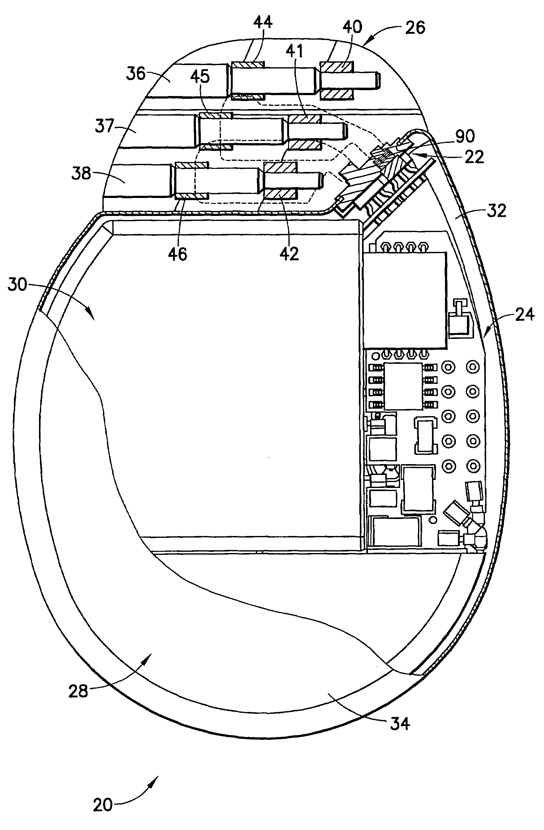
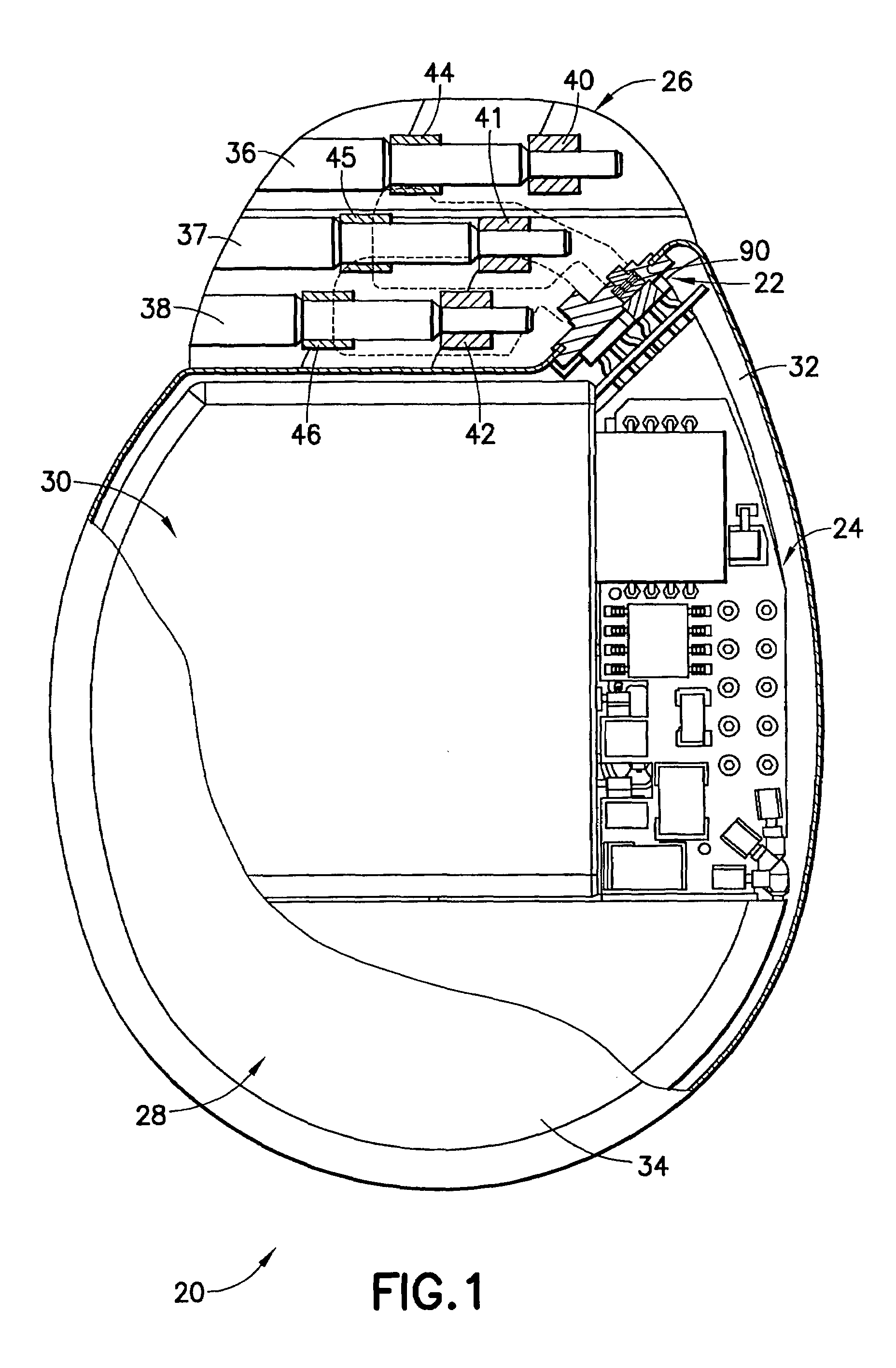
[0039]Referring to FIG. 1, there is shown a perspective view of an implantable medical device 20 in the form of an ICD incorporating features of the present invention. Although the present invention will be described with reference to the embodiments shown in the drawings, it should be understood that the present invention can be embodied in many alternate forms or embodiments. In addition, any suitable size, shape or type of elements or materials compatible with the invention may be used.

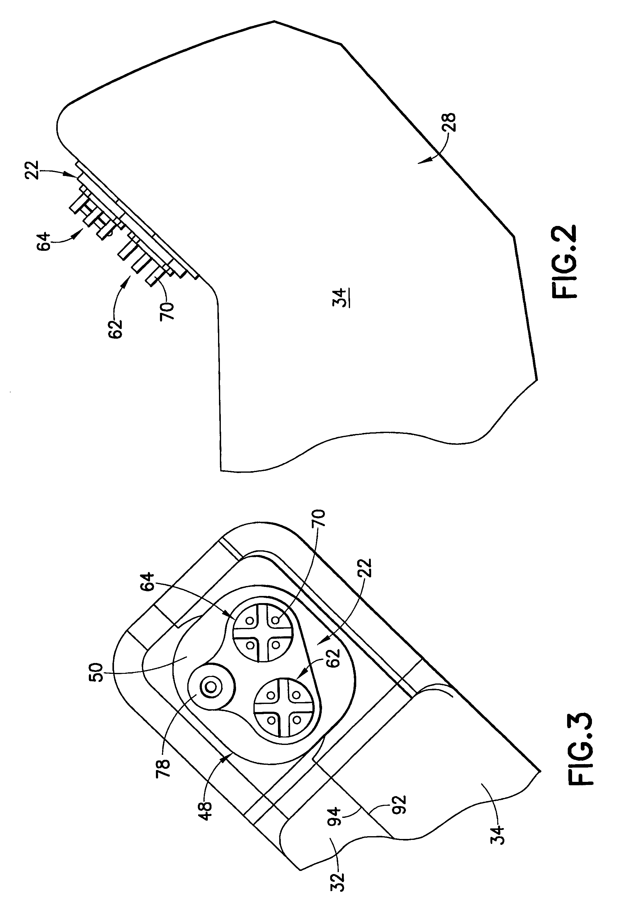
[0040]The ICD 20 In FIG. 1 is seen to include feedthrough apparatus 22 in accordance with the present invention for electrically coupling electronic circuitry 24 of the device 20 to a connector assembly 26 mounted external to the hermetically sealed casing 28. The electronic circuitry 24 is powered by a battery 30, and both the electronic circuitry and the battery are contained within the hermetically sealed casing 28 comprised of opposed wall portions 32, 34. The connector assembly 26, which is mo...


PUM


Abstract

A feedthrough apparatus for a implantable medical device having a casing includes a conductive housing having an outer side, an inner side, and a peripheral surface with a continuous assembly groove therein for mounting on the casing of the implantable medical device. The conductive housing has first and second through bores extending between the outer side and the inner side in spaced apart, generally parallel, relationship. First and second filtered feedthrough assemblies are received, respectively, in the first and second through bores. Each filtered feedthrough assembly includes an insulative terminal, a filter capacitor, and a plurality of lead wires electrically isolated from the conductive housing supported on and extending through the insulative terminal and through the filter capacitor in conductive relation therewith. Also, a backfill port is provided on the conductive housing and has a passageway extending between the inner side and the outer side.

Description

FIELD OF THE INVENTION[0001]The present invention relates generally to implantable medical devices, such as cardiac pacemakers, cardioverters and defibrillators, and more particularly, to a feedthrough apparatus for connecting electronic circuits within an implantable medical device to the connector top and for providing electric field shielding and filtering.BACKGROUND OF THE INVENTION[0002]Although it will become evident to those skilled in the art that the present invention is applicable to a variety of implantable medical devices utilizing pulse generators to stimulate selected body tissue, the invention and its background will be described principally in the context of a specific example of such devices, namely, an ICD or implantable cardioverter-defibrillator for delivering electrical therapy to terminate ventricular tachycardia or ventricular fibrillation via an external connector assembly having lead-receiving receptacles. The appended claims are not intended to be limited, ...

Claims


Application Information

Patent Timeline
Patent Type & Authority Patents(United States)
IPC IPC(8): A61N1/372
CPCA61N1/3754A61N1/3718
Inventor LIM, WISITHAWKINS, RODNEY J.SAHABI, KAVOUS
Owner PACESETTER INC
Why Eureka
Try Eureka