Method and apparatus for reading and controlling electric power consumption

a technology for reading and controlling electric power consumption, applied in the field of utility usage measurement system, can solve the problems of inability to set up devices, inconvenient operation, and high cost for either the utility company or the consumer, and achieve the effect of reducing the number of devices and reducing the cost of installation

Active Publication Date: 2007-08-28
TRENDPOINT SYST
View PDF100 Cites 136 Cited by
  • Summary
  • Abstract
  • Description
  • Claims
  • Application Information

AI Technical Summary

Benefits of technology

[0009]The photoelectric sensor beams a light onto a rotating disk, visible on the face of the meter, whose surface reflects the light. A marker such as a black dot or line placed on the rotating disk absorbs the beamed light resulting in an interval where a lower level of light is being reflected. The photoelectric sensor counts these intervals, representing the number of turns the disk rotates indicating utility usage during a given time period. The apparatus connects to a data-collection unit through a first serial port. The data-collection unit stores the data from the sensor. The serial port connection may also serve to supply power for the apparatus through one otherwise unused pin of that serial connector being assigned as a power carrier, thus avoiding the need for a dedicated power supply. The data collection unit may also be used to store data when the computer is turned off and can be powered by an external 12 volt DC power supply.

Problems solved by technology

However, the majority of methods using optical light-sensing devices are installed inside the existing meter and / or require professional installation.
This process is inefficient and also very costly for either the utility company or the consumer.
A significant disadvantage typical of these devices is that the installation process requires the existing meter to be physically opened and / or the optical light sensing arrangement to be assembled with professional assistance.
Thus, an ordinary consumer generally cannot set up the device, and therefore consumers would have to bear installation costs.
However, the device requires the angle and heights of the light source and sensor to be adjusted in a specific manner using a height adjustment carrier having a collar that must be tightened, which a typical customer most likely would find difficult to accurately adjust.
Furthermore, no provision is made for powering the device and thus further installation problems may be created for the consumer.
Typical drawbacks that are inherent in these systems are that customers cannot see their use in real-time, cannot access this information except when a billing statement is received and, cannot see data except in the standard format chosen by the utility company.
This is useful to protect the power grid from being loaded such that results in a blackout.
However, this system does little to provide feedback to the consumer, let alone provide them with real-time data on their use and cost that allows the consumer to directly shed load voluntarily or with incentive, in order to help the utility balance its load demands.

Method used


Image

  • Method and apparatus for reading and controlling electric power consumption
  • Method and apparatus for reading and controlling electric power consumption
  • Method and apparatus for reading and controlling electric power consumption

Examples


Embodiment Construction

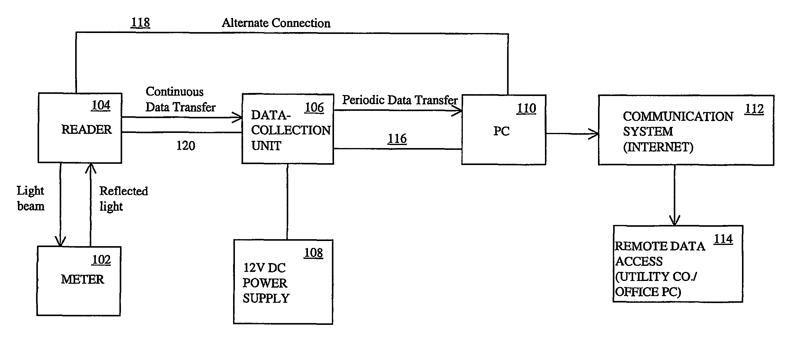
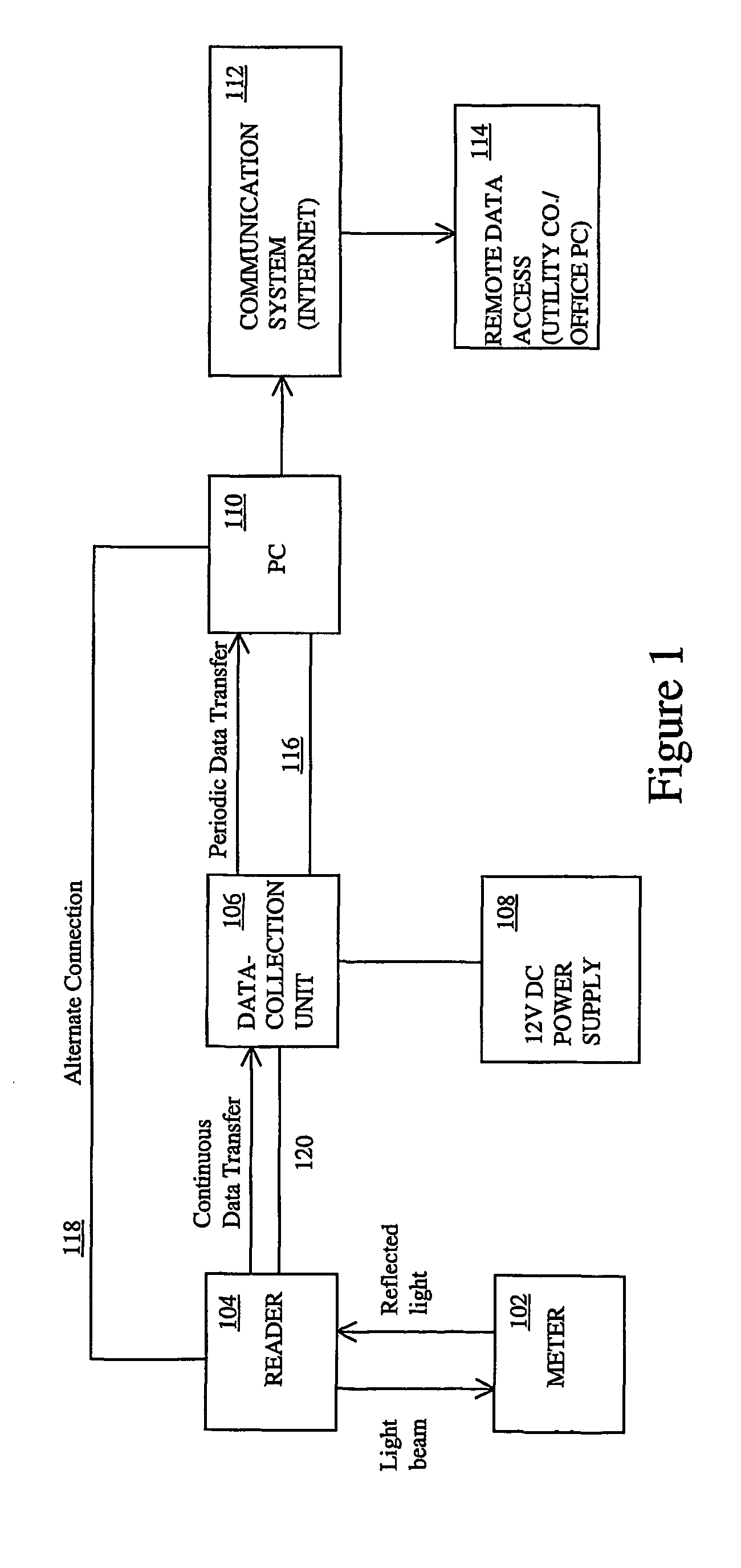
[0024]FIG. 1 illustrates a block schematic diagram of an apparatus 100 for reading and managing power consumption in accordance with the present invention. As shown in FIG. 1, a reader 104 is attached to a typical utility meter 102 such as an analog or digital power meter commonly found on homes, apartment buildings and commercial buildings. The reader 104 provides a means for automatically reading power consumption and may eliminate the need for manually reading the meter 102. The data generated by the reader 104 may be continuously transferred through a connection such as a serial cable 120, to a data collection unit 106 or alternatively directly to the monitoring device 110, such as a computer.

[0025]The data collector 106 is therefore optional. When provided, the data collection unit stores data generated by the reader 104. The data collection unit 106 may store data for a limited time when the monitoring device (computer) 110 is shut off or in the event of a power failure. With ...


PUM


Abstract

An electro-optical, automatic meter reader for enabling a consumer to view and manage power consumption through a browser. A sensor attached to a bracket is mounted to the outside cover of a utility meter without modification of the meter or removal of its housing. A data-collector stores data obtained from the sensor via a serial port which may also provide power for the sensor, thus avoiding use of a dedicated power supply. The data-collector connects to a computer which provides a centralized object through which to view and manage power consumption. The real-time and combined historic data can be used to forecast whether usage will fall above or below a predetermined usage level at the end of a given period of time. In response to a forecast exceeding the level, the computer displays the appropriate graph in a red colored bar within a quantity vs. time chart. The computer may control power consuming devices. A communication system may be established to the system for remote management by the consumer or by the utility company for its own billing and management purposes.

Description

[0001]This application is a national stage application of PCT International application number PCT / US02 / 20961 filed on Jun. 28, 2002. This application and PCT International application number PCT / US02 / 20961 claim priority of US patent application Ser. No. 09 / 896,159 filed on Jun. 28, 2001, which was issued on Sep. 16, 2003 as U.S. Pat. 6,622,097.FIELD OF THE INVENTION[0002]This invention relates generally to a utility usage measurement system, and more particularly to a means of obtaining real-time utility consumption readings and also managing utility consumption by controlling end-use devices from the computer or personal digital assistant (PDA) of the consumer.BACKGROUND OF THE INVENTION[0003]There are various types of automatic meter reading devices (AMR) which use optical light-sensing arrangements to provide remote utility readings for determining utility consumption and for billing purposes. These devices were typically developed as a cost-effective alternative to the existin...

Claims


Application Information

Patent Timeline
Patent Type & Authority Patents(United States)
IPC IPC(8): G06F19/00G01D4/00G01R21/133G01R22/06H02J3/00H02J13/00
CPCG01D4/004G01D4/008G01R21/133G01R22/063H02J13/001H02J3/008Y02B90/242Y02B90/247Y04S20/322Y04S20/50Y02B90/244Y04S20/327Y04S20/46Y04S50/10H02J13/00001H02J2310/12H02J13/00017H02J13/00004Y02B90/20Y04S20/30Y04S40/124Y02E60/00
Inventor HUNTER, ROBERT R.
Owner TRENDPOINT SYST
Why Eureka
Try Eureka