Backlight assembly for directly backlighting displays

a technology for backlighting displays and backlighting components, applied in lighting and heating apparatus, process and machine control, instruments, etc., can solve problems such as serious ill effects, drop in alternating voltage, and difficulty in arranging step-up transformers near

Active Publication Date: 2007-09-04
HANNSTAR DISPLAY CORPORATION
View PDF18 Cites 25 Cited by
  • Summary
  • Abstract
  • Description
  • Claims
  • Application Information

AI Technical Summary

Problems solved by technology

However, transmissive and transflective LCDs require backlighting.
A transmission loss would otherwise occur to cause a drop in alternating voltage.
Besides, interconnecting each of the step-up transformers and one of the cold cathode florescent lamps 34 by extending a high-voltage cable to pass areas between other electrical components might cause serious ill-effect on them.
However, the step-up transformers are difficult to arrange near the high-voltage ends of the cold cathode florescent lamps, respectively.
This difficulty would grow if bulkier step-up transformers are needed to produce higher starting and operating voltages.
However, there are problems if the lamp pitch is greater than the minimum transformer pitch.
The first problem is that an inverter substrate inevitably exceeds the dimension of display screen measured in the vertical direction to thereby cause an increase in size of the entire backlight assembly.
The second problem is in the brightness variance within the display screen such that the brightness becomes less with increased distance from the high-voltage end of each of the cold cathode florescent lamps arranged in parallel thereby resulting in less uniform output distribution.
These problems are posed also in an application where a backlight assembly is required to illuminate two display screens between which the backlight assembly is interposed.

Method used


Image

  • Backlight assembly for directly backlighting displays
  • Backlight assembly for directly backlighting displays
  • Backlight assembly for directly backlighting displays

Examples


Embodiment Construction

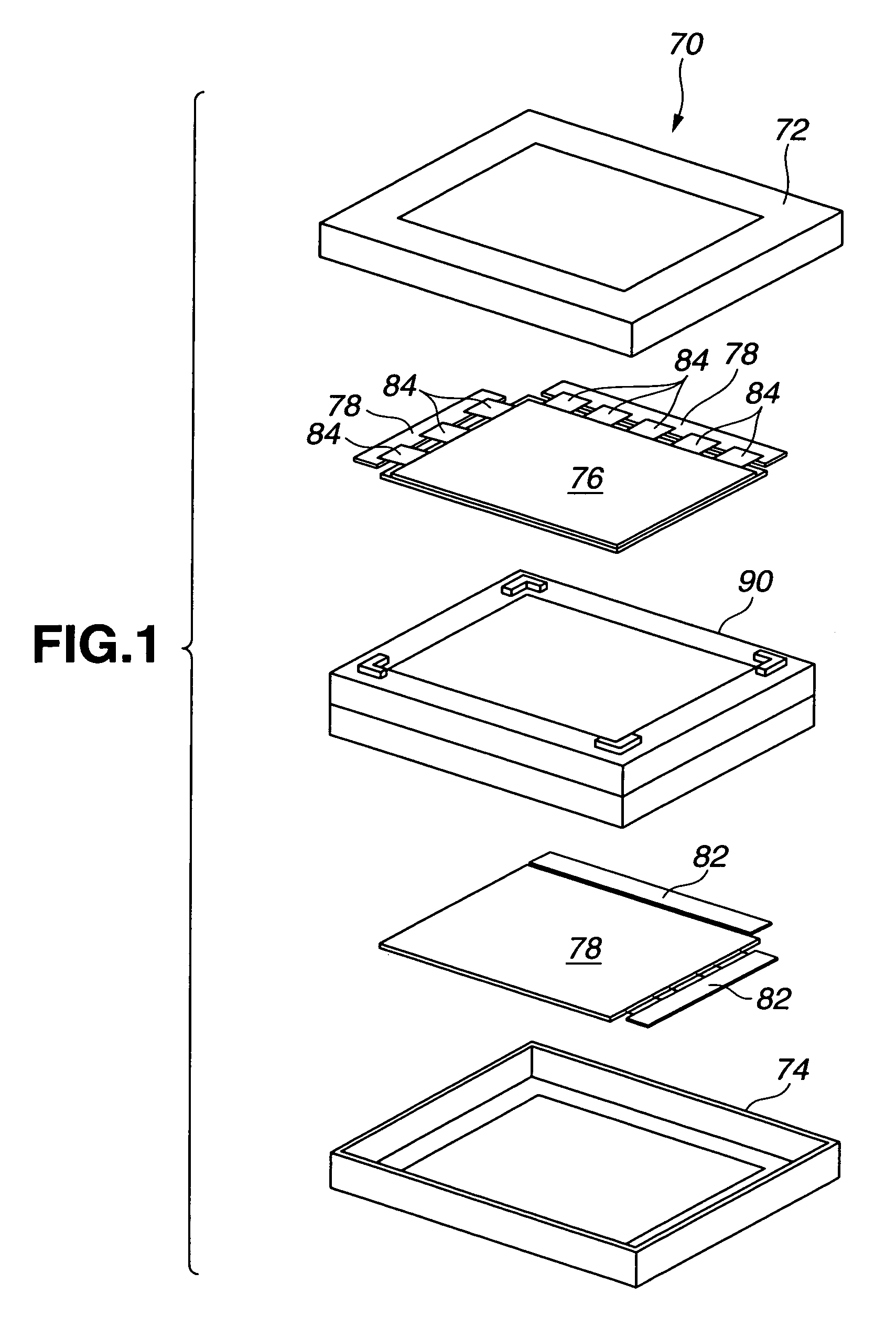
[0030]Referring to the accompanying drawings, FIGS. 1 and 2 illustrate a liquid crystal display (LCD), in which various embodiments of backlight assembly according to the present invention may be applied.

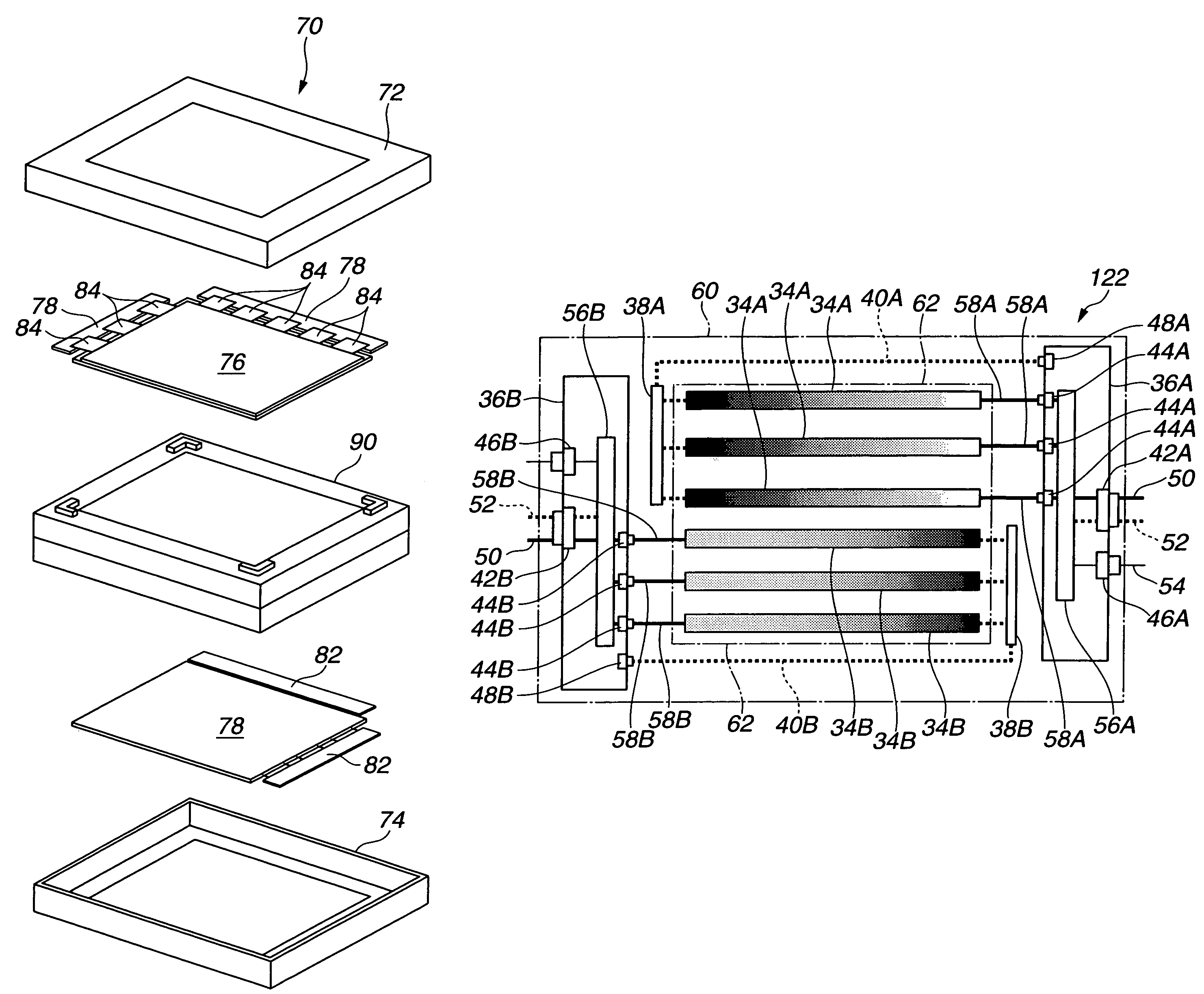
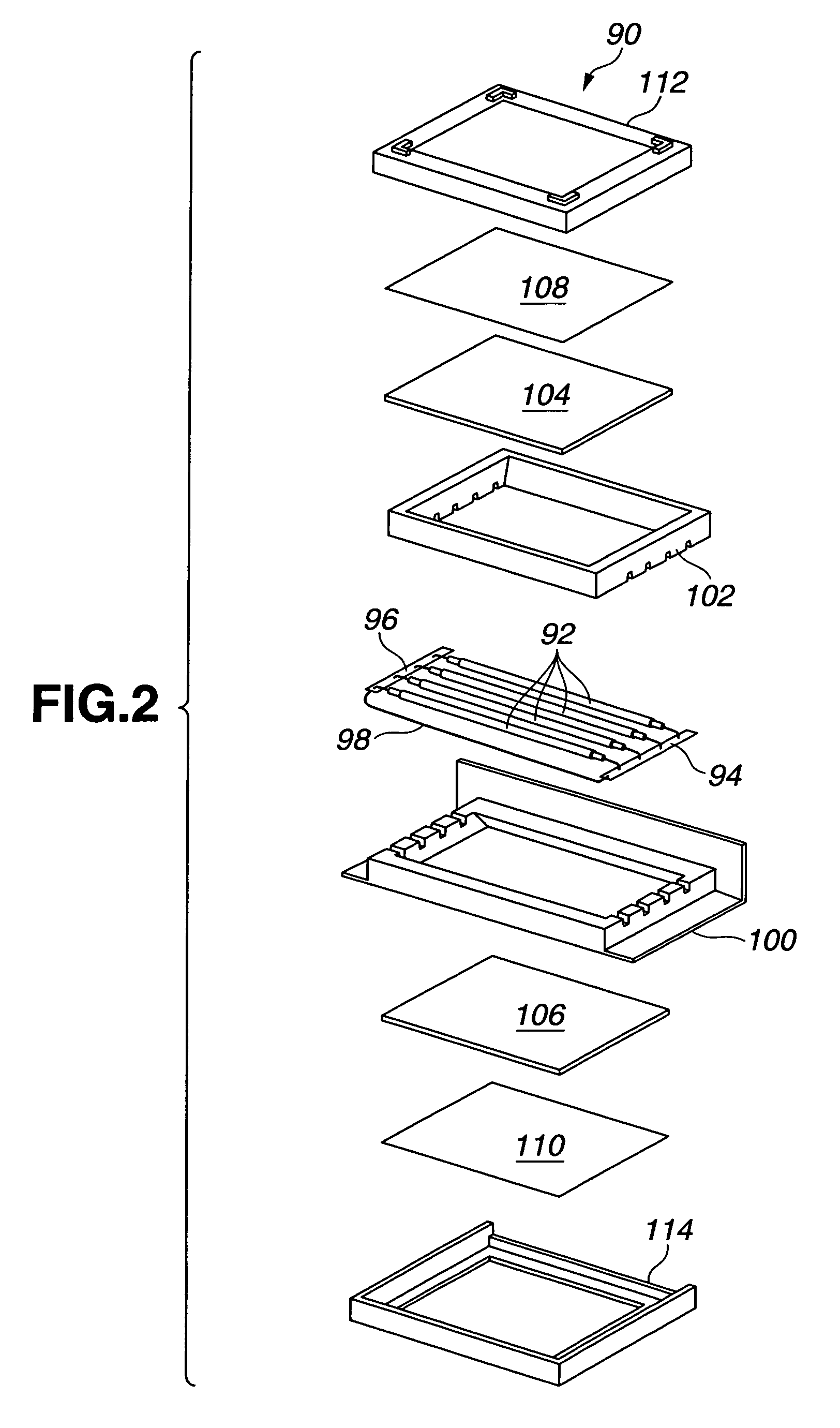
[0031]In FIG. 1, the LCD is generally indicated by the reference numeral 70. The LCD 70 includes a backlight assembly 90. This backlight assembly 90 can illuminate both front and rear surfaces thereof. The LCD 70 includes two LCD panels 76 and 78. The LCD panel 76 is connected via transmission control protocols (TCPs) 84 to two substrates 78. The LCD 78 is connected via TCPs, not shown, to two substrates 82. The LCD 70 also includes front covers 72 and 74 clamped to each other to accommodate therein the backlight assembly 90 and two LCD panels 76 and 78. FIG. 2 illustrates the backlight assembly 90.

[0032]Referring to FIG. 2, the backlight assembly 90 includes a plurality of linear light sources 92 arranged in parallel between an inverter substrate 94 and a return substrate 96. The r...


PUM

PropertyMeasurementUnit
ac voltageaaaaaaaaaa
voltageaaaaaaaaaa

Abstract

A backlight assembly comprises a plurality of linear light sources arranged in parallel behind a display screen. The plurality of linear light sources is divided into a first group and a second group. The linear light sources belonging to the first group are oriented in a first direction. The linear light sources belonging to the second group are oriented in a second direction opposite to the first direction. The backlight assembly comprises a first inverter substrate for driving the linear light sources belonging to the first group, and a second inverter substrate for driving the linear light sources belonging to the second group. The first and second substrates are arranged on one side of the linear light sources and the opposite side thereof, respectively.

Description

BACKGROUND OF THE INVENTION[0001]1. Field of the Invention[0002]The present invention relates to backlight assemblies, and more particularly to backlight assemblies for directly backlighting displays.[0003]2. Description of Related Art[0004]Display devices such as liquid crystal displays (LCDs) are commonly used for displays for many electronic devices such as monitors of office automatic (OA) equipment, and monitors of televisions, all applications where light weight, low power, and a flat panel display are desired. An LCD is essentially a light switching device that does not emit any light on its own and displays information by controlling the state of orientation of the liquid crystal molecules, which in turn controls the transmission of light. LCDs may be divided into three types: reflective, transflective and transmissive. Reflective LCDs use ambient light, and requires no backlighting. However, transmissive and transflective LCDs require backlighting. A backlight or backlights...

Claims


Application Information

Patent Timeline
Patent Type & Authority Patents(United States)
IPC IPC(8): H05B37/02F21S2/00F21V23/00F21Y103/00G02F1/133G02F1/13357G02F1/1345H05B41/24
CPCG02F1/133604G09G3/342G09G3/36G09G3/3426G02F2001/133342G02F2001/133612G09G2330/02G09G2300/023G09G2320/0233G02F1/133342G02F1/133612A61H39/08B65D81/051B65D85/24
Inventor ONO, SHIN-ICHIROUFUKUYOSHI, HIROKAZU
Owner HANNSTAR DISPLAY CORPORATION
Why Eureka
Try Eureka