
Material handling lift vehicle and suspension system for use therewith

a technology for lifting vehicles and materials, applied in the direction of interconnection systems, lifting devices, transportation and packaging, etc., can solve problems such as dampening of system shocks

Inactive Publication Date: 2007-09-11
BEECH ENG & MFG
View PDF9 Cites 18 Cited by
  • Summary
  • Abstract
  • Description
  • Claims
  • Application Information

AI Technical Summary

Problems solved by technology

When the drive wheel travels over the uneven surface, rotational movement in the suspension system causes a vertical movement in the steering column and thus any shocks to the system are dampened.

Method used


Image

  • Material handling lift vehicle and suspension system for use therewith
  • Material handling lift vehicle and suspension system for use therewith
  • Material handling lift vehicle and suspension system for use therewith

Examples


Embodiment Construction

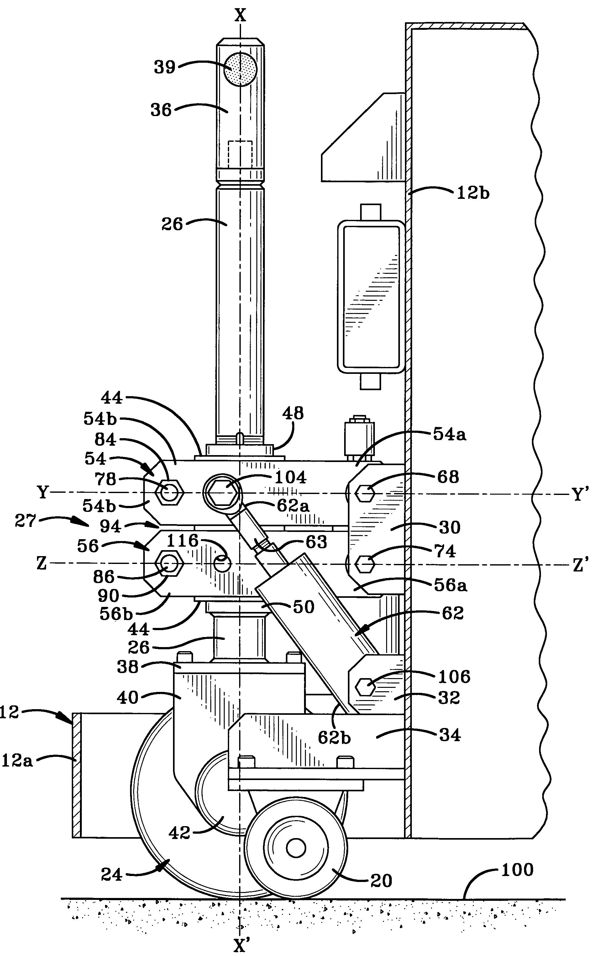
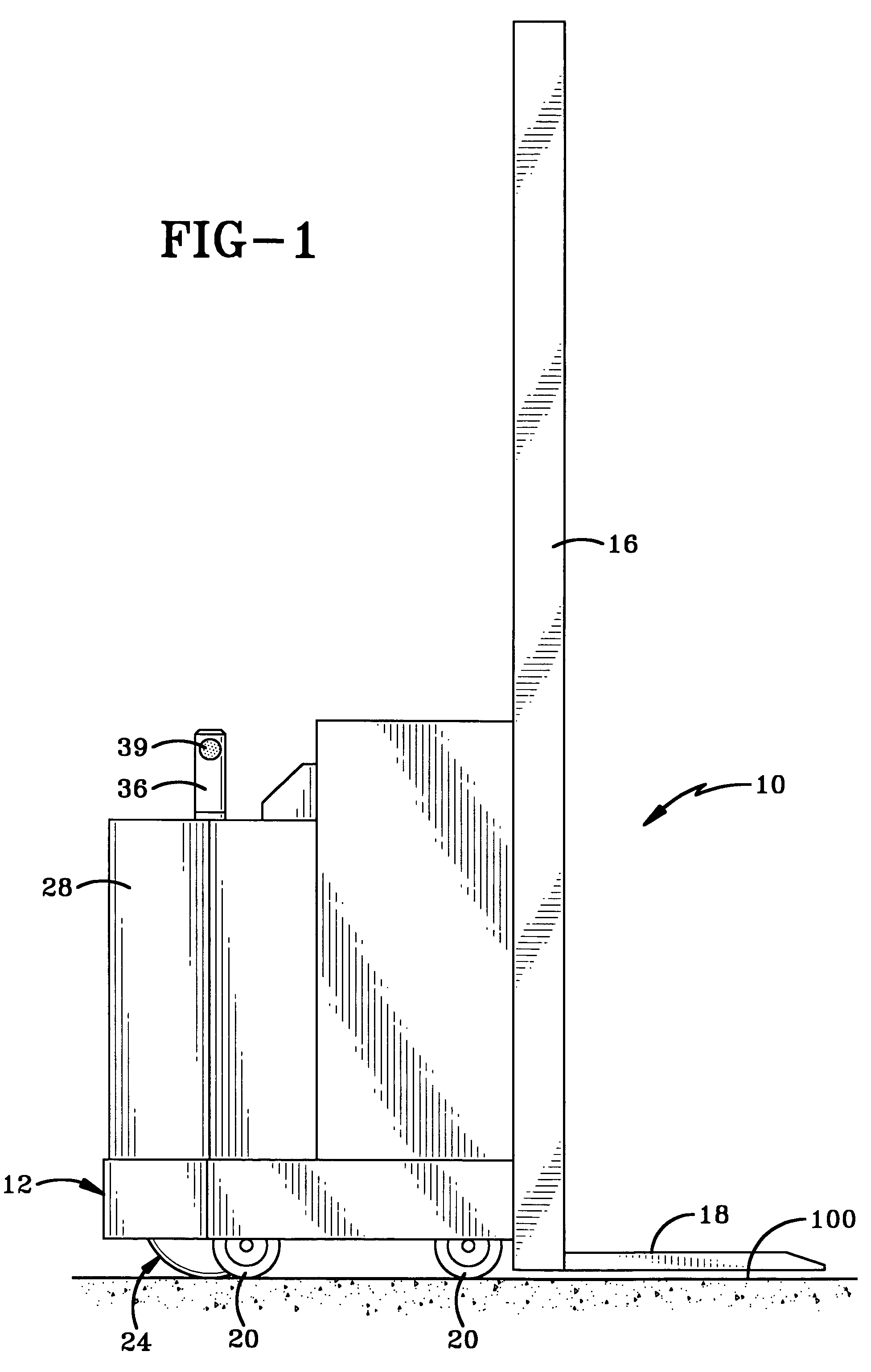
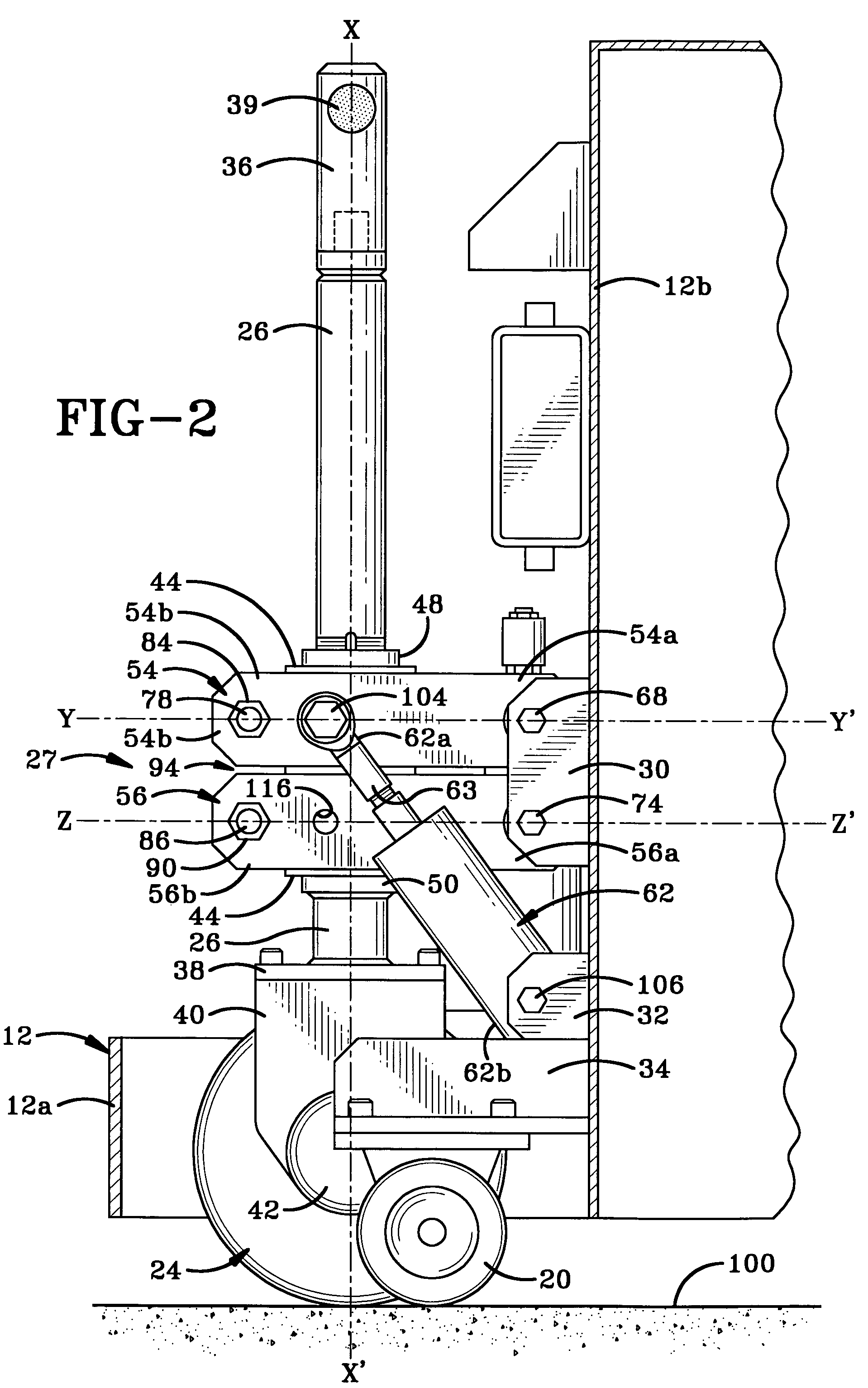
[0023]Referring to FIGS. 1-9, there is shown a material handling lift vehicle, generally indicated at 10. Material handling lift vehicle 10 includes a frame, generally indicated at 12, onto which is mounted a power unit (not shown), a support 16 and a load carrying platform 18. Two pairs of laterally spaced side wheel assemblies 19 and 21, having wheels 20 and 22 respectively, are provided on the underside of frame 12. A non load-bearing drive wheel assembly 24 is connected to a steering column 26 and is positioned intermediate side wheel assemblies 19 and 21. Drive wheel 24 is provided with a parallelogram-style suspension system, generally indicated at 27. Both the power unit (not shown) and suspension system 27 are covered by a hood 28 for protection and to make material handling lift vehicle 10 more aesthetically pleasing.

[0024]Still, referring to FIGS. 1-9, frame 12 includes a horizontal portion 12a and a vertical portion 12b (FIG. 2). A plurality of pairs of support brackets 3...


PUM


Abstract

A material handling lift for moving a load horizontally over a surface and vertically with respect to that surface and a suspension system for the material handling lift. The material handling lift includes a frame with wheels for traveling over the surface. At least one of the wheels is a drive wheel mounted on a vertically-oriented steering column. The steering column is connected to the frame by a parallelogram type suspension system which includes swing arms that are pivotally connected to the frame. A stabilizer bar is connected between the free ends of the swing arms and a shock dampener is connected between the frame and a swing arm. The suspension system helps dampen the shock of traveling over uneven terrain, helps to keep the steering column vertical and the wheels of the vehicle on the ground thereby helping to maintain constant traction with the surface and control of the steering, braking and acceleration of the vehicle. Furthermore, the suspension system aids in providing constant steering effort for the vehicle, regardless of the weight of the load carried.

Description

BACKGROUND OF THE INVENTIONTECHNICAL FIELD[0001]This invention generally relates to vehicles for lifting and transporting materials. More particularly, the invention relates to power-driven walk-behind vehicles that are used to move loads both horizontally over a surface and vertically with respect to the surface. Specifically, the invention relates to a vehicle which includes a suspension system connecting the drive wheel to the frame of the vehicle and which enables the vehicle to travel over an uneven surface.BACKGROUND INFORMATION[0002]Power-driven walk-behind vehicles, such as powered pallet jacks, powered material transfer trucks and powered pallet stackers are commonly used in the manufacturing and retailing industries for moving heavy loads from one location to another within a factory or store and for stacking products on top of each other. When the powered vehicle travels across even terrain, all of its wheels remain in contact with the ground surface and the weight of the...

Claims


Application Information

Patent Timeline
Patent Type & Authority Patents(United States)
IPC IPC(8): B60G3/12
CPCB60G3/185B66F9/07586B60G2200/13B60G2204/129B60G2300/022
Inventor SICA, PATSY L.BECK, JEREMIAH J.
Owner BEECH ENG & MFG
Learn More